
Programming instructions


Chapter 25 Measuring Pulse Width
LabVIEW Data Acquisition Basics Manual 25-2
©
National Instruments Corporation
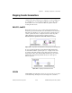
An internal signal is based upon the type of counter chip on your
DAQ device. With DAQ-STC devices, you have a choice between internal
timebases of 20 MHz and 100 kHz. With Am9513 devices, you can choose
internal timebases of 1 MHz, 100 kHz, 10 kHz, 1 kHz, and 100 Hz.
With 8253/54 devices, the internal timebase is either 2 MHz or 1 MHz,
depending on which board you have.
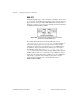
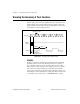
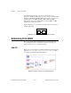
Figure 25-2 shows how to physically connect the counter on your device to
measure pulse width.
Figure 25-2.
Physical Connections for Determining Pulse Width
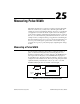
Determining Pulse Width
How you determine a pulse width depends upon which counter chip is
on your DAQ device. If you are uncertain of which counter chip your
DAQ device has, refer to your hardware manual.
DAQ-STC
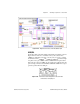
Figure 25-3 shows the diagram of the Measure Pulse-Easy (DAQ-STC) VI
located in
labview\examples\daq\counter\DAQ-STC.llb
, which
uses the Easy VI, Measure Pulse Width or Period.
Figure 25-3.
Diagram of Measure Pulse Width (DAQ-STC) VI
counter
your
device
gate
source
out