
Programming instructions


Chapter 25 Measuring Pulse Width
LabVIEW Data Acquisition Basics Manual 25-6
©
National Instruments Corporation
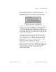
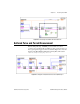
On the example diagram, the first call to ICTR Control VI sets up
counting mode 4, which tells the counter to count down while the gate input
is high. The Get Timebase (8253) VI is used to get the timebase of your
DAQ device. A DAQ device with an 8253/54 counter has an internal
timebase of either 1 MHz or 2 MHz, depending on the device. Inside the
while loop, ICTR Control VI is called to continually read the count register
until one of four conditions are met:
1. The count register value has decreased, but is no longer changing
(it is finished measuring the pulse).
2. The count register value is greater than the previously read value
(an overflow has occurred).
3. An error has occurred.
4. Your chosen time limit has been reached.
After the while loop, the final count is subtracted from the originally loaded
count of 65535 and multiplied by the timebase period to yield the pulse
width. Finally, the last ICTR Control VI resets the counter. Notice that this
VI uses only
Counter 0
. If
Counter 0
has an internal timebase of 2 MHz,
the maximum pulse width you can measure is 2
16
×
0.5
µ
s = 32 ms. For a
complete description of this example, refer to the information found in
Windows»Show VI Info…
.
Controlling Your Pulse Width Measurement
How you control your pulse width measurement depends upon which
counter chip is on your DAQ device. If you are uncertain of which counter
chip you DAQ device has, refer to your hardware manual.
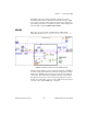
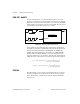
DAQ-STC or Am9513
Figure 25-8 shows one approach to measuring pulse width using the
Intermediate VIs Pulse Width or Period Meas Config, Counter Start,
Counter Read, Counter Stop. You can use these VIs to control when the
measurement of the pulse widths begins and ends. The Pulse Width or
Period Config VI configures a counter to count the number of cycles of a
known internal timebase. The Counter Start VI begins the measurement.
The Counter Read VI determines if the measurement is complete and
displays the count value. After the while loop is stopped, the Counter
Stop VI stops the counter operation. Finally, the General Error Handler VI
notifies you of any errors.