
Programming instructions


Chapter 25 Measuring Pulse Width
LabVIEW Data Acquisition Basics Manual 25-8
©
National Instruments Corporation
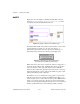
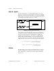
With this example, you can perform four types of buffered measurements:
1. Buffered period measurement, which measures a number of periods in
a pulse train.
2. Buffered semi-period measurement, which measures a number of high
and low pulse in a pulse train.
3. Buffered pulse width measurement, which measures a number of high
or low pulses in a pulse train.
4. Buffered counting, where each rising edge loads the current count into
a finite buffer.
This example uses a single buffer—circular buffering is not supported.
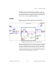
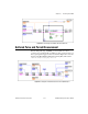
The diagram uses the following Advanced VIs: CTR Group Config,
CTR Buffer Config, CTR Mode Config, CTR Control, and CTR Buffer
Read. CTR Group Config takes the counter and device and sets up a
taskID
. CTR Buffer Config sets up a finite buffer whose size is determined
by the value you enter in
counts per buffer
. CTR Mode Config determines
what type of counting operation to perform based on your choices for
gate
parameters
and
config mode
. CTR Control starts the counting operation,
but does not return until the counting has completed. CTR Buffer Read
reads the buffer of data and returns the values to
buffered counts
. The
buffered times
are determined by dividing the counts by your chosen
timebase
. For a complete description of this example, refer to the
information found in
Windows»Show VI Info…
.
Increasing Your Measurable Width Range
The maximum counting range of a counter, together with the chosen
internal timebase, determine how long of a pulse width can be measured.
Remember the internal timebase acts as the SOURCE. When measuring the
pulse width of a signal, you count the number of source edges that occur
during the pulse being measured. The counted number of SOURCE edges
cannot exceed the counting range of the counter. Slower internal timebases
allow you to measure longer pulse widths, but faster timebases give you a
more accurate pulse width measurement. If you need a slower timebase
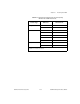
than is available on your counter as shown in Table 25-1, you can set up an
additional counter for pulse train generation and use the OUT of that
counter as the SOURCE of the counter measuring pulse width.