
Programming instructions

Chapter 26 Measuring Frequency and Period
©
National Instruments Corporation 26-7 LabVIEW Data Acquisition Basics Manual
8253/54
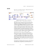
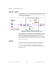
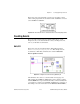
Figure 26-8 shows the Measure Frequency > 1kHz (8253) VI located in
labview\examples\daq\8253.llb
.
Figure 26-8.
Diagram of Measure Frequency > 1 kHz (8253) VI
This VI initiates the counter to count the number of rising edges of a
TTL signal at the CLK of
counter
during a known pulse at the GATE of
counter
. The known pulse is created by
counter 0
, and its width is
determined by
gate width
. The maximum width of the pulse is 32 ms if
your DAQ device has a 2 MHz internal timebase, and 65 ms if your DAQ
device has a 1 MHz internal timebase. This maximum pulse is why this
example only reads frequencies higher than 1 kHz. A frequency of 1 kHz
generates 32 cycles during the 32 ms pulse. As this cycle count decreases
(as with lower frequencies), the frequency measurement becomes less
accurate. Frequency is the output for this example, and period is determined
by taking the inverse of the frequency. You must externally wire the signal
to be measured to the CLK of
counter
, and the OUT of
counter 0
must be
wired through a 7404 inverter chip to the GATE of
counter
.
The diagram of the previous example uses the ICTR Control, Get
Timebase (8253), and Wait + (ms) VIs. The first two ICTR Control VIs
reset
counter
and
counter 0
. The next ICTR Control sets up
counter
to
count down while its GATE input is high. The Get Timebase (8253) VI
returns the internal timebase period for
counter 0
of device. This value is
multiplied by the gate width to yield the count to be loaded into the count
register of
counter 0
. The next ICTR Control VI loads this count and sets
up
counter 0
to output a low pulse, during which cycles of the signal to be
measured are counted.
One advantage of this example is that it only uses two counters. However,
this example has two notable limitations. One limitation is that it cannot
accurately measure low frequencies. If you need to measure lower