
Programming instructions

Chapter 27 Counting Signal Highs and Lows
©
National Instruments Corporation 27-3 LabVIEW Data Acquisition Basics Manual
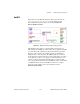
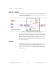
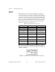
Figure 27-4 shows typical external connections for cascading counters
when counting elapsed time. Notice that the OUT of
counter
is connected
to the SOURCE of
counter+1
.
Figure 27-4.
External Connections to Cascade Counters for Counting Elapsed Time
Counting Events
How you count events depends upon which counter chip is on your
DAQ device. If you are uncertain which counter your DAQ device has,
refer to your hardware documentation.
DAQ-STC
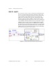
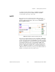
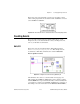
Figure 27-5 shows the Count Events-Easy (DAQ-STC) VI located
in
labview\examples\daq\DAQ-STC.llb
. This example uses the
Count Events or Time-Easy VI which can be found in
Functions»
Data Acquisition»Counter
.
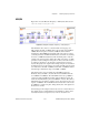
Figure 27-5.
Diagram of Count Events-Easy (DAQ-STC) VI
This VI initiates the counter to count the number of rising edges of a
TTL signal at the SOURCE of
counter
. The counter continues counting
until the
STOP
button is pressed. Remember that you must externally wire
your signal to be counted to the SOURCE of
counter
. For a description of
this example, refer to the information found in
Windows»Show VI Info…
.