
Programming instructions

Chapter 27 Counting Signal Highs and Lows
LabVIEW Data Acquisition Basics Manual 27-6
©
National Instruments Corporation
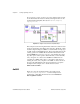
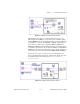
This example uses the following Intermediate VIs: Event or Time Counter
Config, Counter Start, Counter Read, and Counter Stop. The Event or Time
Counter Config VI configures
counter
to count the number of rising edges
of a TTL signal at its SOURCE input pin. The Counter Start VI begins the
counting operation for
counter
. The Counter Read VI returns the count
until the
STOP
button is pressed or an error occurs. Finally, the Counter
Stop VI stops the counter operation. Remember that you must externally
wire your signal to be counted to the SOURCE of
counter
. You can
optionally gate counter with a pulse to control when it starts and stops
counting. To do this, wire your pulse to the GATE of
counter
, and choose
the appropriate
gate mode
from the front panel menu. Additionally, you
can cascade two counters by choosing
two counters (32-bits)
in the
number of counters to use
menu. This will extend your counting range to
over 4 billion. You must also wire the OUT of
counter
to the SOURCE of
counter+1
for this increased counting range. For a complete description of
this example, read the information found in
Window»Show VI Info…
.
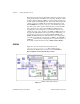
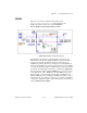
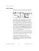
8253/54
Figure 27-9 shows the Count Events (8253) VI located in
labview\examples\daq\8253.llb
. This example uses the
Intermediate VI, ICTR Control which can be found in
Functions»
Data Acquisition»Counter»Intermediate Counter
.
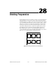
Figure 27-9.
Diagram of Count Events (8253) VI