
Programming instructions

Chapter 27 Counting Signal Highs and Lows
LabVIEW Data Acquisition Basics Manual 27-8
©
National Instruments Corporation
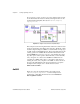
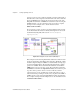
pressed. You do not need to make any external connections. The length of
time that can be counted depends on the maximum count of the counter and
the chosen
timebase
. For example, the 16,777,216 (24-bit) count of the
DAQ-STC and a timebase of 20 MHz can count time for 838 ms. Using the
100 kHz timebase, you can count time for 167 seconds. For a complete
description of this example, refer to the information found in
Windows»Show VI Info…
.
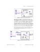
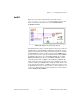
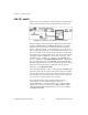
If you need more control over when your elapsed timing begins and ends,
use the Intermediate VIs instead of the Easy VIs. Figure 27-11 shows the
Count Time-Int (DAQ-STC) VI located in
labview\examples\
daq\DAQ-STC.llb
.
Figure 27-11.
Diagram of Count Time-Int (DAQ-STC) VI
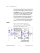
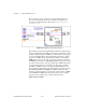
This example uses the following Intermediate VIs: Event or Time Counter
Config, Counter Start, Counter Read, and Counter Stop. The Event or Time
Counter Config VI configures
counter
to count the number of rising edges
of a known internal timebase. The Counter Start VI begins the counting
operation for
counter
. The Counter Read VI returns the count until the
STOP
button is pressed or an error occurs. The count value is divided by
the
timebase
to determine the
elapsed time
. Finally, the Counter Stop VI
stops the counter operation. You do not need to make any external
connections, but you can optionally gate counter with a pulse to control
when it starts and stops timing. To do this, wire your pulse to the GATE of
counter
, and choose the appropriate
gate mode
from the front panel menu.
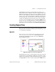
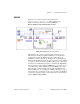
For a complete description of this example, refer to the information found
in
Windows»Show VI Info…
.