
Programming instructions

Chapter 27 Counting Signal Highs and Lows
LabVIEW Data Acquisition Basics Manual 27-10
©
National Instruments Corporation
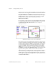
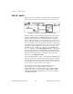
If you need more control over when your elapsed timing begins and
ends, use the Intermediate VIs instead of the Easy VIs. Figure 27-13
shows the Count Time-Int (9513) VI located in
labview\examples\
daq\Am9513.llb
.
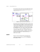
Figure 27-13.
Diagram of Count Time-Int (9513) VI
This example uses the following Intermediate VIs: Event or Time Counter
Config, Counter Start, Counter Read, and Counter Stop. The Event or Time
Counter Config VI configures
counter
to count the number of rising edges
of a known internal timebase. The Counter Start VI begins the counting
operation for
counter
. The Counter Read VI returns the count until the
STOP
button is pressed or an error occurs. The count value is divided by
the
timebase
to determine the
elapsed time
. Finally, the Counter Stop VI
stops the counter operation. You can optionally gate
counter
with a pulse
to control when it starts and stops timing. To do this, wire your pulse to
the GATE of
counter
, and choose the appropriate
gate mode
from the
front panel menu. Additionally, you can cascade two counters by choosing
two counters (32-bits)
in the
number of counters to use
menu. This
extends your elapsed time range. You must also wire the OUT of
counter
to the SOURCE of
counter+1
for this increased range. For a complete
description of this example, refer to the information found in
Windows»Show VI Info…
.