
Programming instructions

Chapter 27 Counting Signal Highs and Lows
©
National Instruments Corporation 27-11 LabVIEW Data Acquisition Basics Manual
8253/54
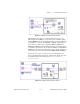
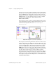
Figure 27-14 shows the Count Time (8253) VI located in
labview\examples\daq\8253.llb
. This example uses the
ICTR Control-Int VI, which can be found in
Functions»
Data Acquisition»Counter»Intermediate Counter
.
Figure 27-14.
Diagram of Count Time (8253) VI
This VI initiates the counter to count the number of rising edges of a
TTL timebase at the CLK of
counter
.
Counter 0
creates the timebase.
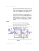
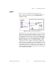
Looking at the diagram, the Timebase Generator (8253) VI sets up
Counter 0
to generate a timebase by dividing down its internal timebase.
The first call to ICTR Control loads the count register and sets up
counter
to count down. Inside the while loop, ICTR Control reads the count, which
is divided by the actual timebase frequency to determine the
elapsed time
.
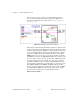
The elapsed time increments until the
STOP
button is pressed or an error
occurs. The last two calls to ICTR Control reset
Counter 0
and counter.
Remember that you must externally wire the OUT of
Counter 0
to the
CLK of
counter
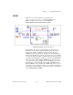
. You can optionally gate
counter
with a pulse to control
when it starts and stops timing. To do this, wire your pulse to the GATE of
counter. For a complete description of this example, refer to the information
found in
Windows»Show VI Info…
.