
Programming instructions

Chapter 28 Dividing Frequencies
LabVIEW Data Acquisition Basics Manual 28-2
©
National Instruments Corporation
DAQ-STC, Am9513
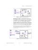
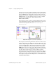
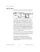
Figure 28-2 shows an example of a signal divider. It uses the Intermediate
counter VIs Down Counter or Divide, Counter Start, and Counter Stop.
Figure 28-2.
Programming a Single Divider for Frequency Division
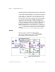
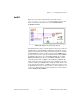
The Down Counter or Divide Config VI configures the specified counter to
divide the SOURCE signal by the
timebase divisor
value and output a
signal when the counter reaches its terminal count (TC). Using Down
Counter or Divide Config VI, you can configure the type of output to be
pulse or toggled. The diagram above outputs a high pulse lasting one cycle
of the source signal once the counter reaches its TC. For more information
on the different types of signal outputs, refer to the Down Counter or Divide
Config VI description in Chapter 27,
Intermediate Counter VIs
, of the
LabVIEW Function and VI Reference Manual
, or the LabVIEW
Online
Reference
, available by selecting
Help»Online Reference…
. The diagram
above counts the rising edges of the SOURCE signal, the default value of
the
source edge
input. In order to figure out where the inputs and outputs
are located on this VI, remember to use the Help window. Open this
window by choosing
Help»Show Help
.
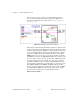
The Counter Start VI tells the counter to start counting the SOURCE signal
edges. The counter only stops the frequency division when the stop button
is pressed. The Counter Stop VI stops the counter immediately and clears
the count register. It is a good idea to always check your errors at the end
of an operation to see if the operation was successful.
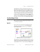
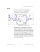
You can alter the Down Counter or Divide Config VI to create a
down counter. To do this, change the timebase value from
0.0
(external SOURCE) to a frequency available on your counter. With the
Am9513 chip, you can choose timebases of 1 MHz, 100 kHz, 10 kHz,
1 kHz, and 100 Hz. With the DAQ-STC chip, you can choose timebases
of 20 MHz and 100 kHz.