
Programming instructions

Chapter 3 Basic LabVIEW Data Acquisition Concepts
©
National Instruments Corporation 3-11 LabVIEW Data Acquisition Basics Manual
are your channels, you can specify a list of channels in a single element by
separating the individual channels by commas—for example,
0, 1, 2
.
Or,because
0
refers to the first channel in a consecutive channel range and
2
refers to the last channel, you can specify the range by separating the first
and last channels with a colon—for example,
0:2
.
Some Easy and Advanced Digital VIs and Intermediate Counter VIs only
need one port or counter to be specified. For more information, refer to the
LabVIEW Function and VI Reference Manual
or the LabVIEW
Online
Reference
. Choose
Help
»
Show Help
and put your cursor on the VI to view
the VI Help window for the VI you intend to use.
LabVIEW recognizes three types of analog channels on a DAQ device:
onboard, AMUX-64T, and SCXI channels. It recognizes two types of
digital ports and counters: onboard and SCXI. This section describes
addressing onboard channels, ports, and counters. AMUX-64T
addressingis described later in Chapter5,
Things You Should Know
aboutAnalogInput
. SCXI channel, port, and counter addressing is
described in Chapter18,
Things You Should Know aboutSCXI
.
Onboard channels refer to analog or digital I/O channels provided by the
plug-in DAQ device. If
x
is an onboard channel, you can specify this by
entering
x
or
OBx
as the
channel list
element. Refer to the description of
your device in your hardware user manual for restrictions on channel order.
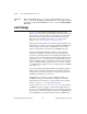
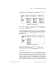
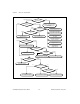
Figure3-7 shows several ways you can address onboard channels
0
,
1
, and
2
. The top three examples apply to VIs whose channel parameters are string
arrays. The bottom two examples apply to VIs whose channel parameters
are scalar strings.
Figure 3-7.
Channel String Array Controls