
Programming instructions

Chapter 3 Basic LabVIEW Data Acquisition Concepts
©
National Instruments Corporation 3-13 LabVIEW Data Acquisition Basics Manual
array element the same settings in the corresponding
limit settings
cluster
array element. Figure 3-8 illustrates one case of this.
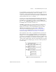
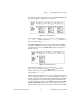
Figure 3-8.
Limit Settings, Case 1
In this example, channels
0:3
(or 0, 1, 2, and 3) are assigned limits of
10.00
to –
10.00
. Channel 4 has limits of
5.00
to –
5.00
. Channels 5, 6,
and 7 have limit settings of
1.00
to
0.00
.
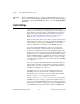
If the
limit settings
cluster array has fewer elements than the
channel
string array, LabVIEW assigns any remaining channels the limit settings
contained in the last entry of the
limit settings
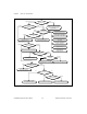
cluster array. Figure 3-9
illustrates this case.
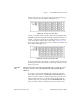
Figure 3-9.
Limit Settings, Case 2
In this example, channels 0, 1, 2, and 3 have limits of
10.00
to –
10.00
.
There are more channels left, but the
limit settings
cluster array is
exhausted. Therefore, the remaining channels (4, 5, 6, and 7) are also
assigned limits of
10.00
to –
10.00
.
The Easy Analog Input VIs have only one pair of input limits. This pair
forms a single cluster element. If you specify the default limit settings, all
channels scanned with these VIs will have identical limit settings. The Easy
Analog Output VIs do not have limit settings. All the Intermediate VIs,
both analog input and output, have the
channel
string array and the
limit
settings
(or
input limits
) cluster array on the same VI. Assignment of
limits to channels works exactly as described above. Refer to the
LabVIEW