
Programming instructions

Chapter 5 Things You Should Know about Analog Input
LabVIEW Data Acquisition Basics Manual 5-4
©
National Instruments Corporation
Choosing Your Measurement System
Now that you have defined your signal, you must choose a measurement
system. You have an analog signal, so you must convert the signal with an
ADC measurement system, which converts your signal into information
the computer can understand. Some of the issues you must resolve before
choosing a measurement system are your ADC bit resolution, device range,
and signal range.
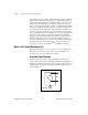
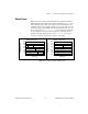
Resolution
The number of bits used to represent an analog signal determines the
resolution
of the ADC. You can compare the resolution on a DAQ device
to the marks on a ruler. The more marks you have, the more precise your
measurements. Similarly, the higher the resolution, the higher the number
of divisions into which your system can break down the ADC range, and
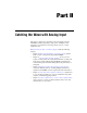
therefore, the smaller the detectable change. A 3-bit ADC divides the
range into 2
3
or 8 divisions. A binary or digital code between 000 and 111
represents each division. The ADC translates each measurement of the
analog signal to one of the digital divisions. Figure 5-4 shows a sine wave
digital image as obtained by a 3-bit ADC. Clearly, the digital signal does
not represent the original signal adequately, because the converter has too
few digital divisions to represent the varying voltages of the analog signal.
By increasing the resolution to 16 bits, however, the ADC’s number of
divisions increases from 8 to 65,536 (2
16
). The ADC can now obtain an
extremely accurate representation of the analog signal.
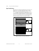
Figure 5-4.
The Effects of Resolution on ADC Precision
16 Bit Versus 3 Bit Resolution
(5kHz Sine Wave)
0 50 100 150 200
Time (µs)
Amplitude (volts)
111
110
101
100
011
010
001
000
8.75
10.00
7.50
6.25
5.00
3.75
2.50
1.25
0
16-bit
3-bit