
Programming instructions

Chapter 5 Things You Should Know about Analog Input
©
National Instruments Corporation 5-5 LabVIEW Data Acquisition Basics Manual
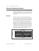
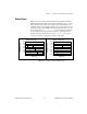
Device Range
Range refers to the minimum and maximum analog signal levels that the
ADC can digitize. Many DAQ devices feature selectable ranges, so you can
match the ADC range to that of the signal to take best advantage of the
available resolution. For example, in Figure 5-5, the 3-bit ADC, as shown
in the left chart, has eight digital divisions in the range from 0 to 10 volts.
If you select a range of –
10.00
to
10.00
volts, as shown in the right chart,
the same ADC now separates a 20 volt range into eight divisions. The
smallest detectable voltage increases from
1.25
to
2.50
volts, and you
now have a much less accurate representation of the signal.
Figure 5-5.
The Effects of Range on ADC Precision
Range = 0V to 10V
0 50 100 150 200
Time (µs)
Amplitude (volts)
111
110
101
100
011
010
001
000
8.75
10.00
7.50
6.25
5.00
3.75
2.50
1.25
0
Range = -10V to 10V
0 50 100 150 200
Time (µs)
Amplitude (volts)
111
110
101
100
011
010
001
000
7.50
10.00
5.00
2.50
0
-2.50
-5.00
-7.50
-10.00