
Programming instructions

Chapter 5 Things You Should Know about Analog Input
LabVIEW Data Acquisition Basics Manual 5-6
©
National Instruments Corporation
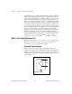
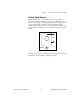
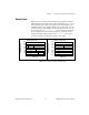
Signal Limit Settings
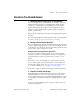
Limit settings are the maximum and minimum values of the signal you are
measuring. A more precise limit setting allows the ADC to use more
digital divisions to represent the signal. Figure 5-6 shows an example of
this theory. Using a 3-bit ADC and a device range setting of
0.00
to
10.00
volts, Figure 5-6 shows the effects of a limit setting between 0 and
5 volts and 0 and 10 volts. With a limit setting of 0 to 10 volts, the ADC
uses only four of the eight divisions in the conversion. But using a limit
setting of 0 to 5 volts, the ADC now has access to all eight digital divisions.
This makes the digital representation of the signal more accurate.
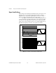
Figure 5-6.
The Effects of Limit Settings on ADC Precision
Limit Settings 0 to 10V
Limit Settings 0 to 5V
10.00
8.75
7.5
6.25
5.00
3.75
2.50
1.25
0.00
111
110
101
100
011
010
001
000
V
10.00
8.75
7.5
6.25
5.00
3.75
2.50
1.25
0.00
V
000
001
010
011
100
101
110
111
Limit Settings 0 to 5V