
Programming instructions

Chapter 5 Things You Should Know about Analog Input
LabVIEW Data Acquisition Basics Manual 5-8
©
National Instruments Corporation
For more information on the device range and limit settings for your device,
refer to the tables in Appendix B,
Hardware Capabilities
, in the
LabVIEW
Function and VI Reference Manual
, or to the LabVIEW
Online Reference
,
available by selecting
Help»Online Reference…
. In these tables, there is
information on gain settings for each device. For more information on gain,
refer to the
Limit Settings
section of Chapter 3,
Basic LabVIEW Data
Acquisition Concepts
.
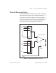
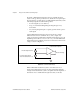
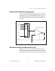
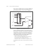
Now that you know which kind of ADC to use and what settings to use
for your signal, you can connect your signals to be measured. On most
DAQ devices, there are three different ways to configure your device to
read the signals: Differential, Referenced Single-Ended (RSE), and
Non-Referenced Single-Ended (NRSE).
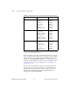
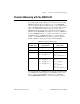
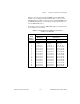
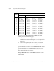
Table 5-1.
Measurement Precision for Various Device Ranges and Limit Settings
Device Voltage Range Limit Settings Precision
1
0 to 10V 0 to 10 V
0 to 5 V
0 to 2.5 V
0 to 1.25 V
0 to 1 V
0 to 0.1 V
0mV to 20 mV
2.44mV
1.22 mV
610 µV
305 µV
244 µV
24.4 µV
4.88 µV
–5 to 5V –5 to 5V
–2.5 to 2.5 V
–1.25 to 1.25 V
–0.625 to 0.625 V
–0.5 to 0.5 V
–50mV to 50 mV
–10mV to 10 mV
2.44 mV
1.22 mV
610 µV
305 µV
244 µV
24.4 µV
4.88 µV
–10 to 10V –10 to 10 V
–5 to 5 V
–2.5 to 2.5 V
–1.25 to 1.25 V
–1 to 1 V
–0.1 to 0.1 V
–20mV to 20 mV
4.88 mV
2.44 mV
1.22 mV
610 µV
488 µV
48.8 µV
9.76 µV
1
The value of 1 LSB of the 12-bit ADC. In other words, the voltage increment corresponding
to a change of 1 count in the ADC 12-bit count.