
Programming instructions

Chapter 6 One-Stop Single-Point Acquisition
©
National Instruments Corporation 6-7 LabVIEW Data Acquisition Basics Manual
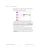
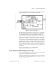
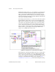
The following diagram shows how to perform software-timed analog I/O
using the AI Read One Scan and AO Write One Update VIs.
Figure 6-7.
Software-Timed Analog I/O
The AI Read One Scan VI configures your DAQ device to acquire data
from analog input channels 0 and 1. Once your program acquires a data
point from channels 0 and 1, it performs calculations on the data and
outputs the results through analog output channels 0 and 1. Because the
iteration count is connected to the AI Read One Scan and AO Write One
Update VIs, the application configures the DAQ device for analog input
and output only on the first iteration of the loop. The loop rate as well as
the acquisition rate is specified by
loop rate
. The reason why the
actual
loop period
is important is because user interaction affects the loop and
acquisition rate. For example, pressing the mouse button interrupts the
system clock, which controls the loop rate. If your analog acquisition rate
for control loops does not need to be consistent, then use software-timed
control loops.
For more control examples, refer to the VIs located in
examples\daq\solution\control.llb
.
Using Hardware-Timed Analog I/O Control Loops
For a more precise timing of your control loops, and more precise analog
input scan rate, use hardware-timed control loops.
An example of hardware-timed, non-buffered control loops is the Analog
IO Control Loop (hw timed) VI located in
labview\examples\daq\
anlog_io\anlog_io.llb
.