
Programming instructions

Chapter 6 One-Stop Single-Point Acquisition
LabVIEW Data Acquisition Basics Manual 6-8
©
National Instruments Corporation
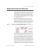
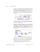
With hardware-timed control loops, your acquisition is not interrupted by
user interaction. Hardware-timed analog input automatically places the
data in your DAQ device FIFO buffer at an interval determined by the
analog input scan rate. You can synchronize your control loop diagram to
this precise analog input scan rate by repeatedly calling the AI Single Scan
VI to read the oldest data in the FIFO.
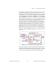
The AI Single Scan VI returns as soon as the next scan has been acquired
by the DAQ Device. If more than one scan is stored in the DAQ device
FIFO when the AI Single Scan VI is called, then the LabVIEW diagram
was not able to keep up with the acquisition rate. You can detect this by
monitoring the data remaining output of the AI Single Scan VI. In other
words, you have missed at least one control loop interval. This indicates
that your software overhead is preventing you from keeping up with your
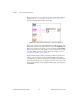
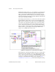
hardware-timed loop rate. In Figure 6-8, the
loop too slow
Boolean
indicator is set to TRUE whenever this occurs.
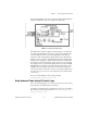
Figure 6-8.
Analog IO Control Loop (HW-Timed) VI Block Diagram
In this diagram, the AI Config VI configures the device to acquire data on
channels 0 and 1. The application does not use a buffer created in CPU
memory, but instead uses the DAQ device FIFO.
input limits
(also known
as
limit settings
) affects the expected range of the input signals. For more
information on input limits (limit settings), refer to Chapter 3,
Basic
LabVIEW Data Acquisition Concepts
. The AI Start VI begins the analog