
Programming instructions


Chapter 7 Buffering Your Way through Waveform Acquisition
©
National Instruments Corporation 7-5 LabVIEW Data Acquisition Basics Manual
For many DAQ devices, the same ADC samples many channels instead of
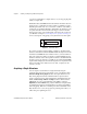
only one. The maximum sampling rate per channel is
The scan rate input in all the VIs described above is the same as the
sampling rate per channel. To figure out your maximum scan rate, you
must divide the maximum sampling rate by the number of channels.
In Appendix B,
Hardware Capabilities
, in the
LabVIEW Function
and VI Reference Manual
, maximum sampling rates are listed for each
DAQ device. You also can refer to the LabVIEW
Online Reference
,
available by selecting
Help»Online Reference…
.
Note
When using the NB-A2100 or the NB-A2150 boards, specifying an odd buffer size
or an odd number of samples when acquiring data with one channel results in
–10089 badTotalCountErr. To avoid this error, specify an even number of
samples and throw away the extra sample.
Simple-Buffered Analog Input Examples
Following are several different examples of simple-buffered analog input.
Simple-Buffered Analog Input with Graphing
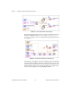
Figure 7-5 show how you can use the AI Acquire Waveforms VI to acquire
two waveforms from channels 0 and 1 and then display the waveforms on
separate graphs. This type of VI is useful in comparing two or more
waveforms, or in analyzing how a signal looks before and after going
through a system. In this illustration, 1,000 scans of channels 0 and 1 are
taken at the rate of 5,000 scans per second. The
Actual Scan Period
output
displays in the actual timebase on the x-axis of the graphs. Remember that
each column of the 2D array contains the information for each channel.
maximum sampling rate
number of channels
-----------------------------------------------------------------