Manual de Usuario / User’s Manual æro 50 & LX-218 Antes de utilizar el equipo, lea la sección “Precauciones de seguridad” de este manual. Conserve este manual para futuras consultas. Before operating the device, please read the “Safety precautions” section of this manual. Retain this manual for future reference.
æro 50 LX-218 & LX-218R
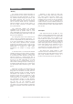
aero 50 Precauciones de Seguridad Safety Precautions Caja acústica pasiva / Passive loudspeaker enclosure El signo de exclamación dentro de un triángulo indica la existencia de importantes instrucciones de operación y mantenimiento en la documentación que acompaña al producto. Conserve y lea todas estas instrucciones. Siga las advertencias.
LX-218 & LX-218R Precauciones de Seguridad Safety Precautions Caja acústica pasiva / Passive loudspeaker enclosure El signo de exclamación dentro de un triángulo indica la existencia de importantes instrucciones de operación y mantenimiento en la documentación que acompaña al producto. Conserve y lea todas estas instrucciones. Siga las advertencias.
DECLARACIÓN DE CONFORMIDAD DECLARATION OF CONFORMITY D.A.S. Audio, S.A. C/ Islas Baleares, 24 - 46988 - Pol. Fuente del Jarro - Valencia. España (Spain).
GARANTÍA Todos nuestros productos están garantizados por un periodo de 24 meses desde la fecha de compra. Las garantías sólo serán válidas si son por un defecto de fabricación y en ningún caso por un uso incorrecto del producto. Las reparaciones en garantía pueden ser realizadas, exclusivamente, por el fabricante o el servicio de asistencia técnica autorizado. Otros cargos como portes y seguros, son a cargo del comprador en todos los casos.
CONTENTS SYSTEM DESCRIPTION 3 LINE DRAWINGS 3 RIGGING SYSTEM 4 Warning Description ASSAMBLING AN ARRAY 7 CONFIGURATIONS 12 SPECIFICATIONS 18 Manual del Usuario / aero 50, LX-218 & LX-218R / User’s Manual
Manual del Usuario / aero 50, LX-218 & LX-218R / User’s Manual
Four 8MN, 8” speakers arranged on a V shape, incorporating 2.5” EFW voice coils, Neodymium magnet assemblies and TAF cooling system are used for mid-range reproduction. High frequencies are handled by two M-75N high frequency compression drivers with 3” EFW coil, Neodymium magnet and 1.5” exit coupled to twin serpisTM plane wave guide, designed by DAS Audio. The serpisTM plane wave adaptor also serves as a heat sink for the compression driver. LINE DRAWINGS 1350 592 627 The D.A.S.
RIGGING SYSTEM Warning This manual contains needed information for flying DAS Audio line array systems, description of the elements and safety precautions. To perform any operations related to flying the system, read the present document first, and act on the warnings and advice given. The goal is to allow the user to become familiar with the mechanical elements required to fly the acoustic system, as well as the safety measures to be taken during set-up and teardown.
A) AX-AERO50 G2A48 QUICK RELEASE PIN 8X30 (6 UNITS PER BOX) G1A50 To aid the setting of the G2A48 guide in the corresponding hole in the top box, each hole is labeled with an associated angle, both for stacked and flown applications. To fit the guides into the holes, highly resistant 8 mm quick release pins with a ball safety lock are used. FLY Weight: 51 kg {112.2 lb} Dimensions (Al x An x Pr): 342 x 1440 x 721 (mm.) {H x W x D: 13.5” x 56.7” x 28.4”} WLL: 1700 kgf 8º 8º 6.4º 6.4º 4.8º 4.8º 3.
D) AX-COMBO12 Safety factors The AX-COMBO12 is a rigging adapter to be used when aero 12A units are needed to be flown under aero 50 units as dowfill systems. Maximum 6 aero 12A units can be flown from this rigging grid. The AX-COMBO12 includes front and rear steel guides which permit variation of the angle between it and the last aero 50 cabinet in the cluster. Angles vary from 1.8º to 9.6º.
ASSEMBLING AN ARRAY Transporting the cabinets To facilitate transport, the aero 50 units are equipped with a PL-50 front dolly panel attached by means of the rigging hardware. The front dolly panel is useful when rigging systems. The LX-218R units can be moved by way of the PL-LX218 front dolly panel attached by means of the rigging hardware or by way of the PL-218S, a dolly for vertically stacking (up to 3 units). The LX-218 units can be moved by way of the PL-218S.
Once the first box has been placed at 0º and raised approximately 75cm (30 in) the second box of the array can be placed nearby. Once located in position, the G2A48 guides of the second box should be freed and inserted in the rear located receiving points of the suspended box and secured with the safety pins. Once the splay angle between the first two boxes has been determined, the front of the box can be lifted into place.
Once the boxes have been joined, the front dolly panels can be removed. The next boxes should be attached “one by one” using the methods described. Finally, the array should be hoisted to the correct height and secured with slings to avoid swinging. This method is more time consuming than assembling an array by the “all at once” procedure, but is appropriate for situations due to a lack of space in which to array the system.
The complete assembly should begin being lifted from the hoist (3) so that the rear of the enclosures come together due to their trapezoidal shape. The hoist will be used only to take up slack in the chain, all the weight should be on the hoist. Proceed in this manner until the wheels of the last enclosure are off the ground. From here on, the array can now be lifted with the hoist.
6 7 Once the complete array has been lifted into place, additional slings should be attached to secure the array and avoid swinging. To lower the system, both hoists should be used until the lowest box is about 1 meter from the ground. From there on, only the front hoist should be used so that the array assembly begins to lean forward, at the same time, the PL-50 platforms should be reattached.
12 x aero 50 8 LX-218 Subs: left & right SUB LINK LINK LOW MID HIGH LINK LINK HIGH FP 10000 Q FP 10000 Q FP 10000 Q SUB FP 10000 Q FP 10000 Q FP 10000 Q MID LOW LINK LINK EDIT LINK LINK 12 DSP-4080 CONFIGURATIONS Manual del Usuario / aero 50, LX-218 & LX-218R / User’s Manual
6 aero 50A 60m - 196,8ft Manual del Usuario / aero 50, LX-218 & LX-218R / User’s Manual 13
LINK LINK LINK DSP-4080 LINK FP 10000 Q SUB_1 SUB_2 EDIT DSP-4080 FP 10000 Q SUB_2 FP 10000 Q SUB_1 EDIT FP 10000 Q FP 10000 Q HIGH MID LOW LINK LINK LINK LINK LINK LOW MID HIGH FP 10000 Q FP 10000 Q 16 x aero 50 12 x LX-218 Center Cardioid Subs LINK LINK LINK 14 Manual del Usuario / aero 50, LX-218 & LX-218R / User’s Manual
8 aero 50A 72m - 236,2ft Manual del Usuario / aero 50, LX-218 & LX-218R / User’s Manual 15
LINK LINK LINK LINK LINK LINK LINK LINK 24 x aero 50 16 LX-218 Center Cardioid Subs EDIT MID LOW SUB_1 SUB_2 FP 10000 Q FP 10000 Q FP 10000 Q FP 10000 Q SUB_2 FP 10000 Q FP 10000 Q FP 10000 Q FP 10000 Q LINK LINK LINK HIGH LOW MID HIGH SUB_1 LINK LINK LINK DSP-4080 EDIT LINK LINK DSP-4080 FP 10000 Q 16 FP 10000 Q FP 10000 Q FP 10000 Q FP 10000 Q Manual del Usuario / aero 50, LX-218 & LX-218R / User’s Manual FP 10000 Q
12 aero 50A 87m - 285,4ft Manual del Usuario / aero 50, LX-218 & LX-218R / User’s Manual 17
18 aero 50 Birch Plywood Black Paint Integrated in box design 2 x NL8 wired as LF1±1, LF2±2, MF±3, HF±4 47.5 x 135 x 62.7 cm (18.7 x 53.1 x 24.7 in) 85 kg (187 lbs) AX-aero50 Bumper Ax-Combo12 Rigging Adapter PL-50 Dolly Panel (included) Enclosure Material Color/Finish Rigging System Connectors Dimensions (H x W x D) Manual del Usuario / aero 50, LX-218 & LX-218R / User’s Manual 55 x 128 x 65 cm (22 x 51 x 26 in) 78 kg (171.
UM_AE50_01 www.dasaudio.com D.A.S. AUDIO, S.A. C/. Islas Baleares, 24 46988 Fuente del Jarro Valencia, SPAIN Tel. 96 134 0525 Tel. Intl. +34 96 134 0860 Fax 96 134 0607 Fax Intl. +34 96 134 0607 D.A.S. AUDIO OF AMERICA, INC. Sunset Palmetto Park 6816 NW 77th Court. Miami, FL. 33166 - U.S.A. TOLL FREE: 1-888DAS4USA Tel. +1 305 436 0521 Fax +1 305 436 0528 D.A.S. AUDIO ASIA PTE. LTD. 25 Kaki Bukit Crescent #01-00/02-00 Kaki Bukit Techpark 1 Singapore 416256 Tel.