
Installation manual

© Hills Industries 2009 Page 8
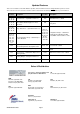
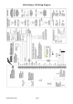
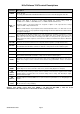
Hills Reliance 128 Terminal Descriptions
Terminal Description
EARTH
Earth / Ground.
To comply with ACA S009 & AS/NZS3000:2000. Connect to the 16.5V AC plug pack earth wire.
AC
AC input. Connect a 16.5V, 25 VA, 40 VA or 50 VA approved transformer.
BELL + &
BELL -
Built in siren driver, if used as a siren output (default), the speaker rating should be
15 Watt at 8 or 16 Ohm, or 30/40 Watt at 4, 8, or 16 Ohm, 250mA maximum load.
If voltage output is selected in Feature 22 - Segment 2 - Option 1, this output becomes voltage
output, 12 VDC, 1 Amp maximum load.
Note: A 3.3K
resistor may be required across the bell terminals when a 12 VDC siren is used.
If no resistor is used, you may experience voltage leakage into the siren that will cause these devices
to output a small signal.
KP DATA
Connect the to the KP data terminal on the code pads and the expanders (usually blue or green
wire). Maximum total wire run is 800 metres using 14/020 cable. These numbers are for one code
pad at the end of the wire. When connecting more than one code pad to the system bus wire, a
higher gauge wire will be required, or there will be a reduction in maximum wire distance. Maximum
32 devices.
KP COM
Connect to the Common terminal on the code pads and the expanders (usually the black wire).
KP POS
Connect to the Positive terminal on the code pads and the expanders (usually the red wire).
The KP POS and AUX PWR + terminals are limited to 1 Amp total current when added together.
SMOKE+
Smoke detector power 12VDC, 500mA maximum.
COM
Connect negative wire of powered devices such as motion detectors and smoke detectors.
AUX PWR+
Connect positive wire of all powered devices except smoke detectors and code pads.
This terminal and KP POS are limited to 1 Amp total current when added together.
ZONE 8
Connect to one side of zone 8 loop. Connect the other side to a COM terminal. Open or short causes
alarm. Zone 8 may be used for a two-wire smoke detector using a 680 E.O.L. resistor. See Feature
22.
COM
Common (-) terminal for zones 7 & 8. (See the wiring diagram for examples)
ZONE 7 -
ZONE 1
Connect to one side of zone loop. Connect the other side to a COM terminal. Open or short causes
alarm. Only zone 8 can be a two-wire smoke zone. (See the wiring diagram for examples)
AUX
RELAY
OUT 1-2
Relays one and two switch a 12 volts output on their N/C and N/O terminals. This means that you
connect the positive lead of your device to these terminals, and connect the negative lead to a COM
terminal. Ensure your device does not exceed the ratings of these relays, max 400 mA per output,
max 800 mA total output.
AUX
OUT 3-4
Auxiliary outputs 3 and 4 (in addition to 1 & 2) are located on a pin header J7, see wiring diagram for
details.
Battery
Leads
Connect black (-) and red (+) leads to a 12VDC sealed lead acid rechargeable battery.
Do not connect to a dry cell battery.
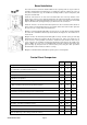
Warning: Total standby current drawn from SMOKE +, KP POS and AUX PWR +, must not exceed
700 mA with 16 VAC 3 Amp Plug Pack or 400 mA with 16 VAC 1.5 Amp Plug Pack.