
Installation manual

© Hills Industries 2009 Page 5
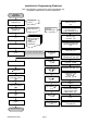
Note
–
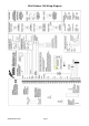
This diagram is a guide for basic system programming only.
Configuration depends upon customer requirements
Installation & Programming Flowchart
Program Phone 1 (4#)
Account code (5#)
Report Format (6#) p 24
Program Event Reports (9#)
& No. Dial Attempts (10#)
p 25
Set Phone Line Cut
Delay (11#) p 25
Program Area 1 Options (16#)
& Entry/Exit Time (17#) p 27
Change Installer Code (1#) &
Duress Code (3#)
p
23
Program Zones 1-8 (18#)
& Area allocation (19#) p 29
Default System
Programming
p 21
Customer
User Details p 63
via code pad (or DL900 software)
Program System Options
(22#) p 32
For Multiple Area Systems
see F37-58 p 40-44
Program Phone 2 (7#)
& Phone 3 (8#)
if required p 25
Program Zones 9-16
(20#, 21#) p 31
Zones 17-48
(59# - 66#) p 44 -45
Program Siren/
Communication Attempts
(23#) & Code Pad Sound
Options (24#) p 35
Program System Timers (25#)
p 35
Program Autotest Time &
Freq. (32#) p 39
Plan & quote
installation p 62
Order modules and
hardware p 4
Install cabling
p 7
Mount equipment
Program system
p 20
Customer
Requirements
Train customer to use
system
Test user codes
Walk test sensors
( Chime) p 19
Test timers
(siren, entry, exit, etc)
(44)
Test phone numbers
(Cent Stn. & mobiles)
(
44
)
Test battery back up
(44)
System Handover
Planning Sheet
see p 63
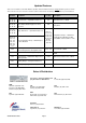
DAS order form/s
ACA Cabler
Electrical Contractor
Security License
(NSW)
or other local
re
q
uirements
Program System
Date (96)
p 16
Program Code Pad
No. & Areas (94)
p 16
Program Code Pad
Options (93)
p 15
Program System
Time (97)
p 16
Exit Program Mode
p 20
Program User
Codes (5)
p 17