Programmer’s Manual for 7106, 7206 and 7010 Series DMX® Emulation
The Programmer's Manual is designed for the following printers: 7106, 7206, 7206-300 and 7010 Series Copyright © August 2010, DASCOM Europe GmbH
Chapter 1 Command Interpreter and Command System 1.1 Outline 1-2 1.2 Outline of Command System 1-2 1.3 Outline of Interpreter 1-4 1.4 Outline of Label Format Data 1-5 1.5 Outline of Label Printing Method 1-7 1.6 Control Code Specification 1-8 1.6.1 System Level Immediate Execution Commands 1-9 1.6.2 System Level Occasional Execution Commands 1-14 1.6.
1.1 Outline Generally, when labels of graphics and bar codes are printed by a line printer, print data is converted into bit map data in the computer and transmitted to the printer for printing. In this process the host computer has to generate the bit map data and send it to the printer, this reduces throughput leading to slow printing and host computer operation.
Fig. 1 Command summary System level commands Start with "SOH" or "STX" and end with a “CR” Commands which start with "SOH" Executed as soon as they are received (For example: printing halt, output of printer status, etc.) Commands which start with "STX" Executed in order after they are received into the reception buffer (For example: sensor maintenance, etc.
1.3 Outline of Interpreter Two types of interpreters are used for this printer; system level and label format interpreters. When power is turned on, the system level interpreter is selected and the data received is processed in the system level interpreter and system level commands are executed. Changing to the label format interpreter to start generating label data is executed with system level commands.
1.4 Outline of Label Format Data This printer prints label format data by using memory space of the following size. area Reception buffer area [bytes] Model 7206 7106 7010 16K Field register data area [bytes] 20K Number of maximum print fields 400 Global register area [bytes] 1K Bit map area [bytes] Maximum page length [inches] 1 1892K 32 Reception buffer area The reception buffer area is a ring data buffer area (software FIFO) under software control.
4 Bit map area The bit map area is a buffering area for output data. The data in this area is generated by a rasterizer according to the data in the field data area and corresponds to individual dots that are generated on the label during printing. The data of the bit map area is printed on the label with high quality and at high speed by means of the printer control program and exclusive thermal control circuit.
1.5 Outline of Label Printing Method This printer has two label printing methods, one is that all label format data received is printed, and the other is that format data which has been received beforehand, is printed or partially modified and printed. 1 2 All data received method ・ ASCII code "STX" + "L" sets the printer to label format mode. The printer clears the field register area and control is transferred from the system level interpreter to the label format interpreter.
1.6 Control Code Specification 1 Outline ・ This printer is connected to the computer via a serial interface and prints characters and bar codes at the requested print position on the label. ・ The printer has a data area of 20,000 characters.
1.6.1 System Level Immediate Execution Commands These commands are executed as soon as the printer receives them. They begin with "SOH," i.e. [01].
Command reset Code [01] # Function Initialized equivalent to power is turned on. Buffer and on-board memory contents are initialized. Command setting for previous commands is initialized. Transmission data (XOFF) T (XON) Caution Since printer executes reset immediately after receiving this command, it clears un-printed data in the reception buffer. When using this command, you are recommended to check printing completion first, then send this command.
Printer status Relationship between command interpreter, batch processing and printing Normal label printing puts the printer in the above status. The printer, however, operates with a double buffer, so if the next printing data is received during batch processing, both interpreter operation and batch processing (printing) may be performed simultaneously.
Transmission of number of remaining sheets to be issued Code [01] E Function If this command is received, printer will send data on the number of remaining sheets to be issued for the current printing to the computer with 4 ASCII characters. The [0D] hex code is added to the end of the 4-digit transmission data. Caution Printer sends data on the number of remaining sheets to be issued to the computer as soon as it receives this command (in a period of approx. 150ms - 250ms).
Error status transmission request (4-byte packet) Code [01] I Function After receiving this command, printer sends 4-byte data on current conditions inside the printer to the host PC. Shown below are contents of the 4-byte data to be sent from the printer.
1.6.2 System Level Occasional Execution Commands These commands are executed as soon as the printer receives them. They begin with "STX," i.e. [02].
Printing quality test pattern [02] T Rewriting specified format register contents [02] U Setting memory switch contents [02] V Printer version number transmission request [02] v Information-in-memory-module transmission request [02] W Testing flash memory [02] w Default module selection [02] X Clearing memory module contents (in file units) [02] x TrueType fonts Symbol Set Selection [02] y Printing printer status [02] Z Select Command Set [02][1B] G Setting printing methods [02][1B] M
Setting date and time Code [02] A, w, mm, dd, yyyy, hh, MM, j j j Setting w Sun. 0 Fri. 5 mm Month 01 - 12 dd Day 01 - 31 yyyy Year 4 digits hh Hour (24-hour display) MM Minute 00 - 59 jjj Spare 000 fixed Mon. 1 Sat. 6 Tues. 2 Weds. 3 Function Sets date and time on the calendar stored in the printer. Example Input data below represents 15:30 Saturday 7 July 2001. Input data [02]A6070720011530000 Thurs.
Date and time transmission request Code [02] B Data format w, mm, dd, yyyy, hh, MM, j j j w Sun. 0 Fri. 5 Mon. 1 Sat. 6 Tues. 2 Weds. mm Month 01 - 12 dd Day 01 - 31 yyyy Year 4 digits hh Hour (24-hour display) MM Minute 00 - 59 jjj Total number of days from the 1st of January 3 Thurs. 4 Function Data on the contents of the calendar (date and time) stored in the printer is transmitted to the computer. Data format transmitted from the printer is described below.
Setting paper length for continuous paper Code [02] c nnnn Unit 0.01 inch Setting nnnn 4-digit data Inch system Metric system Initialization value: 0000 0001 – 9999 (0.01 – 99.99 inches) 0001 – 9999 (0.1 – 999.9 mm) Function Sets label length for continuous paper. Length of label format is specified with this command. Label is cut in the length with this setting when using auto-cutter. When using label paper, 0000 must be set. Example Example of input data below represents paper length of 2.
Setting two-page edit mode (double buffer) Code [02] d Function After receiving this command, printer divides the internal edit buffer into 2 pages and enters the high-speed edit mode. In the high-speed edit mode, editing the next page in advance while the current page is being printed increases printing speed. Caution The printer automatically judges whether the double buffer is needed or not, and the mode is switched accordingly, so this command does not need to be particularly specified.
Changing number of prints for edited format Code [02] E nnnn Setting nnnn Function Specifies changing of number of prints for formatted or formerly printed label format. Example Input data below represents that after ending label format printing data "ABC" one sheet, the number of prints is set to 3 by using this command and printing is executed with [02] G command. (In this case, the number of prints is one plus three.
Setting edge sensor selection Code [02] e Function Changes paper position detection sensor to transparent-type. Used for detecting paper gap between label papers, die-cut paper, notch hole for tag paper, etc. This setting is used as default. Caution If not detected properly, check the sensor position. Example Paper gap between label papers and notch holes for tag paper in Fig below is detected.
Setting peeling (cutting) position Code [02] f nnn Units 0.01 inch (0.1mm) Setting nnn 3-digit data Initial value and its set range vary depending on the command setting.
Figure Cutter Ejection Peeler Print head Paper sensor A B C Note: Peeler option is not available for CLP-8301 Printing edited or formerly-printed format Code [02] G Function Prints label data for former printing or formatting. Caution This command is effective only when label data for former printing or formatting is left in the internal memory. If power is turned off or reset is performed, data in the internal memory will be cleared, so this command will not be effective.
Graphics data block input command Code [02] I m a f name, data Transmission data m Storing memory module specification Allocation of modules varies with command settings. Refer to the table below.
7-bit image loading file format 7-bit image data uses ASCII format data. In this example, 7-bit image data with the file name of “MARK7” is stored in the memory card and printed out. Value of inside [ ] is shown in hex format.
8-bit image format 8-bit image data uses ASCII format data. In this example, 8-bit image data with the file name of “MARK8” is stored in the memory card and printed out. Value of inside [ ] is shown in hex format. (Note: Data below is described in hex.
Download of TrueType Font Code [02] i m T nn name xxxxxxxx data… Transmission data m Storing memory module specification Allocation of modules varies with command settings. Refer to the table below.
Pause per label printing Code [02] J Function Performs pause each time label is printed one sheet. Used when label peeling detection sensor is not mounted on the printer incorporating peeling function. Pause is cancelled by pressing Pause key on the control panel. Caution To clear this function, reset the printer.
Extension system command (printer settings) Code Transmission data [02] Kdabc Printer setting parameter a Hex notation for the following bit settings bit 0-2 baud rate case bit 4 = 0 0=9600*, 1=600, 2=2400, 3=4800, 5=300, 6=1200, 7=9600 test mode case bit 4 = 1 0=115200, 1=57600, 2=38400, 3= none, 5=none, 6= none 7= none bit 3 character length 0=8 bits*, 1=7 bits bit 4 Extended baud rate 0=OFF*, 1=ON bit 5 (not used) always 0 bit 6 (fixed) always 1 bit 7 (fixed) always 0 b Hex notation for the following b
P: 115200 baud, 8-bit length, no parity @: thermal transfer, no peeling sensor, no auto-cutter B: continuous paper Setting peeling (cutting) position Code [02] Kf nnnn Units 0.01 inch (0.1mm) Setting nnnn 4-digit data Inch system 0001 - 9999 (0.01 – 99.99 inches) Metric system 0001 - 9999 (0.1 – 999.9 mm) Function/ Caution Command is valid only for DMI/DMW mode. It has the same function as that of [02] fnnn. For details, refer to [02] fnnn command.
Specifying printing contents setting start Code [02] L Function With this command input, printer enters the label format mode and waits for input of printing contents definition and label format commands until it receives "E" "s" or "X" code. Example Input data below represents that label format command input is started, data "ABC" is defined as printing contents, label format command input is completed, and label printing command "E" is entered.
Setting maximum label length Code [02] M nnnn Units 0.01 inch or 0.1 mm Setting nnnn 4-digit data Initialization value: 1000 (10.00 inches) Max. value: Inch system 9999 (99.99 inches) Metric system 9999 (99.9 mm) Function Sets maximum label length for detecting label out. If printer cannot detect the next top of the label within the maximum label length which has been set with this command, "M" command error occurs. Set value 2.5 to 3 times as large as the label length to be used.
Changing units from inch to metric system Code [02] m Function Changes units for all-distance-specified-command-parameters from 0.01 inch to 0.1 mm. With reset, units are set to metric system. Example Input data below represents that data "ABC" is specified with units in metric system.
Setting printing position Code [02] O nnnn Units 0.01 inch or 0.1 mm Setting nnnn 4-digit data Initial value and its set range vary depending on the command set. Inch system Metric system Command Set Initial value Minimum value Max value Initial value Minimum value Max value DMI / DMW DM4 / DM8 DPP 0220 0220 0110 0120 0120 0010 0320 0320 0210 0559 0559 0279 0305 0305 0025 0813 0813 0533 Function Specifies the distance between paper sensor and print head.
Paper cut Code [02] o Function When mounting auto-cutter, if this command is received, the label or paper cutting will be performed once. Caution If auto-cutter is not turned to ON, this command will be ignored. Set the cutting sheet number to 0 (zero) with the specified command (cnn or :nnnn). Otherwise, each label will be cut automatically. Setting dump mode start Code [02] P Function By receiving this command, printer enters the dump mode.
Pause in occasional execution Code [02] p Function Executes pause occasionally. Caution Pause on and off cannot be performed with this command. Cancelling pause must be operated from the Pause key on the control panel. Clearing all memory module contents Code [02] Q Function Clears all data in on-board flash memory and on-board SD-RAM and option memory card modules. Caution Clearing of all memory module contents takes about 15 seconds.
Clearing memory module contents Code [02] q n Setting n Memory module specification parameter Allocation of modules varies with command settings. Refer to the table below. Command Set Allocation of module DMI / DMW DM4 / DM8 DPP on-board S D-RAM D A B on-board flash memory G B A PCMCIA Card (option) E or F E or F E or F Current memory module on-board on-board on-board SD-RAM SD-RAM SD-RAM Function Clears all data in memory module.
Setting reflective paper sensor selection Code [02] r Function Detects label position automatically by reflective paper sensor. Reflective paper sensor detects black lines that are printed on the back of the label and understands the label position. In default, reflective paper sensor is selected. Caution When detection is not performed properly, check the sensor position. Example As shown in the figure below, label position is detected with the black lines on the back of the label.
Setting paper feed speed Code [02] Sa Setting a Paper feed speed specifying character A or B or 1 2.0 inches (50.8 mm)/sec C or D or 2 2.0 inches (50.8 mm)/sec E or F or 3 3.0 inches (76.2 mm)/sec G or H or 4 4.0 inches (101.6 mm)/sec I or J or 5 5.0 inches (127.0 mm)/sec K or L or 6 6.0 inches (152.4 mm)/sec M or N or 7 7.0 inches (177.8 mm)/sec O or P or 8 8.0 inches (203.2 mm)/sec Q or R or 9 9.0 inches (228.6 mm)/sec S or T or a 10.0 inches (254.0 mm)/sec U or V or b 11.
Setting one-page edit mode (single buffer) Code [02] s Function After receiving this command, printer makes the internal edit buffer one page. At this time, the maximum printing length on one page is 40 inches. In initialization after turning on power, this mode is set. Caution The printer automatically judges whether the single buffer is needed or not, and the mode is switched accordingly, so this command does not need to be particularly specified. Maximum printing length per page is 40 inches.
Rewriting specified format register contents Code [02] U nnaa.. Setting nn 2-digit format register numbers 01 - 99 Printer sets format register numbers in sequence when label format is executed. aa Input character string data ending with CR code (0D hex) instead of old data. Basically the number of characters must be the same as the old data. But if it is small, rewriting can be executed. Function Changes some part of the formerly printed label format or formatted label contents and prints it again.
Setting memory switch contents Code [02] V n Setting n is hex data expressing switch on and off with binary. Appropriate ASCII codes are used for setting. Bit Auto-cutter 0 1 1 O Ribbon end sensor Peeling sensor 2 3 4 O 5 6 O 7 O Not care 3 O O O O Function With this command, memory switch contents can be changed temporarily. Example When auto-cutter is turned to ON, n = 1 (binary 0001), i.e., 1 for hex, so ASCII code 31hex is set.
Information-in-memory-module transmission request Code [02] W n Setting n F, G, L F Transmits downloading font information. G Transmits graphic image file information. L Transmits format (label printing contents) information. Function Transmits file name and memory remaining capacity in the currently installed memory module to the computer in ASCII code. Caution The [0D] hex is added to the end of the transmission code. Example Reception data below represents that file name "ABC.
Default module selection Code [02] X a Setting a Default module selection Allocation of modules varies with command settings. Refer to the table below. Command Set Allocation of module DMI / DMW DM4 / DM8 DPP on-board S D-RAM D A B on-board flash memory G B A PCMCIA Card (option) E or F E or F E or F Current memory module on-board on-board on-board SD-RAM SD-RAM SD-RAM Function Selects default module.
Clearing memory module contents (in file units) Code [02] xntname Transmission data m Memory module specification parameter Allocation of modules varies with command settings. Refer to the table below.
TrueType font symbol set selection Code [02] ySxx Setting S S fixed xx Specification of a symbol set The character sequence of 2 figures (Refer to the following table for a setting value.) Function Selection of a TrueType font symbol set Caution It depends on each TrueType font file for the symbol set which becomes actually effective. Example PC-850 multilingual is chosen.
Printing printer status Code [02] Z Function Performs test printing for indicating printer status. Select Command Set Code [02] [1B] G n Setting n 0, 1,2 0 : DMI or DMW 1 : DM4 or DM8 2 : DPP Function Selects proper command set for your application. Caution Switching command sets will change the designated destination of memory module and paper position. Check the command set if something is wrong with the destination and location of files.
Setting Printing Method Code [02] [1B] Mn Setting n T , D T : Thermal transfer D : Heat-sensitive Function Designates the printing method to be set; thermal transfer mode where a ribbon is used, or heat-sensitive mode where heat-sensitive paper is used. Example Shown below are examples of input data when printing in thermal transfer mode. Input data [02] n [02][1B] MT Sets units to inch Sets printing method to thermal transfer mode.
Setting ejection (tear-off) Code [02] [1B] tn Setting n 0 , 1 0 : Ejection is turned to OFF 1 : Ejection is turned to ON Function Switches ejection ON and OFF. The contents with this command are stored in the backup memory and kept valid even if the power is turned off. Caution When the auto-cutter and peeling sensor are turned to ON, any ejection is not performed even if ejection is turned to ON because the auto-cutter and peeling sensor have priority.
Setting label width Code [02] [1B]w nnnn In inch unit mode, nnnn is defined as nn.nn inch, in metric unit, nnnn is defined as nnn.n mm Unit 0.01 inch or 0.1 mm Setting nnnn 4-digit data Initialization value: depending on the printer Inch system 0000 – 9999 (0 inch - 99.99 inches) Metric system 0000 – 9999 (0 mm - 999.9 mm) Note: Maximum setting value will be different depending on the the printer model . Function Sets label width. Width of label format is specified with this command.
1.6.3 Label Format Commands The following commands will be valid if the label format command interpreter is turned on with "STX" + "L," i.e. [02] L.
Setting number of prints for same label ^ Setting number of cuts (4-digit) : Character field definition 1n.. Bar code field definition Ruled line definition 1X..L Box definition 1X..B Polygon definition 1X..P Circle definition 1X..C Graphics printing definition 1Y.. Reading out from global register 1n.. [02]S Date and time printing definition 1n..
Set format attribute Code An Setting n 1, 2, 3, 5 1 : All data should be formed by XOR processing In this mode, the area where text strings, images or barcodes intersect will not be printed. 2 : All data should be formed by OR processing. In this mode, the area where text strings, images or barcodes intersect will be printed.
Setting offset in direction of column Code C nnnn Units 0.01 inch or 0.1 mm Setting nnnn 4-digit data Initialization value: 0000 Inch system 0000 - 9999 (0.00 inch - 99.99 inches) Metric system 0000 - 9999 (0.0 mm - 99.9 mm) Function Sets offset value for printing start position in direction of column (paper left and right) to adjust the position of the total printing contents. Example Shifts label printing position 1.0 inch (C0100) rightward and prints.
Setting number of cuts (2-digit) Code c nn Setting nn Function After printing specified number of labels, cuts paper. Caution This command is invalid unless the auto-cutter is installed and it is turned to ON. Since the initialization value is 01 (one sheet), if the auto-cutter is ON, each label sheet will be cut automatically. When the label is cut by using the paper cut command (o), this must be set to 0 (zero) sheet.
Setting pixel size in horizontal and vertical direction Code D hv Units One dot Setting h Dot size in horizontal direction 1, 2 v Dot size in vertical direction 1, 2, 3 0.127 mm or 0.005 inch Note: Initialization value will be varied by the Print Res. DPI (DP mm) set by the operation panel. Command Set DMI / DMW DM4 / DM8 DPP Initialization value 11 22 11 Function Specifies pixel size (dot formation units) in the range of 1 dot x 1 dot to 2 dots x 3 dots.
Completion of setting printing contents (field preparation) and printing labels Code E Function Completes printing contents setting and prints labels. On completion of printing, command interpreter is switched to system level interpreter and system level commands are valid. Caution If label format commands are used again, use the system level "STX" + "L" command.
Changing units from inch to metric system Code m Function Changes units temporarily for all-distance-specified-command-parameters from 0.01 inch to 0.1 mm. Example Input data below represents that data "ABC" is specified with units in metric system. Changing units from metric to inch system Code n Function Changes units temporarily for all-distance-specified-command-parameters from 0.1 mm to 0.01 inch. Operation is same as [02] n command.
Setting printable area speed Code Pa Setting a One alphanumeric character. A or B or 1 2.0 inches (50.8 mm)/sec C or D or 2 2.0 inches (50.8 mm)/sec E or F or 3 3.0 inches (76.2 mm)/sec G or H or 4 4.0 inches (101.6 mm)/sec I or J or 5 5.0 inches (127.0 mm)/sec K or L or 6 6.0 inches (152.4 mm)/sec M or N or 7 7.0 inches (177.8 mm)/sec O or P or 8 8.0 inches (203.2 mm)/sec Q or R or 9 9.0 inches (228.6 mm)/sec S or T or a 10.0 inches (254.0 mm)/sec U or V or b 11.0 inches (279.
Setting backfeed speed Code pa Setting a One alphanumeric character. A or B or 1 2.0 inches (50.8 mm)/sec C or D or 2 2.0 inches (50.8 mm)/sec E or F or 3 3.0 inches (76.2 mm)/sec G or H or 4 4.0 inches (101.6 mm)/sec I or J or 5 5.0 inches (127.0 mm)/sec K or L or 6 6.0 inches (152.4 mm)/sec M or N or 7 7.0 inches (177.8 mm)/sec O or P or 8 8.0 inches (203.2 mm)/sec Q or R or 9 9.0 inches (228.6 mm)/sec S or T or a 10.0 inches (254.0 mm)/sec U or V or b 11.0 inches (279.
Specifying space between characters Code [1b] P nn Setting nn Amount of space between characters 00 - 99 Data in [ ] is hex. Initialization value: 00 Function Adds specified space between characters to all characters. Example Input data below represents that data without specification of space between characters and data with specification of 10 to space between characters are set and printed.
Setting number of prints Code Q nnnn Setting nnnn Function Sets number of sheets to be printed. Example Input data below represents that the same contents of labels are printed ten sheets.
Setting offset in direction of row Code R nnnn Units 0.01 inch or 0.1 mm Setting nnnn 4-digit data Initialization value: 0000 Inch system 0000 - 9999 (0.00 inch - 99.99 inches) Metric system 0000 - 9999 (0.0 mm - 99.9 mm) Function Sets offset value for printing start position in direction of row (paper top and bottom) to adjust the position of the total printing contents. Example Shifts label printing position 1.0 inch (R0100) upwards and prints.
Calling label format Code r aa..a Setting aa..a Function Calls label format stored in the memory module. Storing of label format into memory module is executed with "s" command.
Setting unprintable area speed Code Sa Setting a One alphanumeric character. A or B or 1 2.0 inches (50.8 mm)/sec C or D or 2 2.0 inches (50.8 mm)/sec E or F or 3 3.0 inches (76.2 mm)/sec G or H or 4 4.0 inches (101.6 mm)/sec I or J or 5 K or L or 6 5.0 inches (127.0 mm)/sec 6.0 inches (152.4 mm)/sec M or N or 7 7.0 inches (177.8 mm)/sec O or P or 8 8.0 inches (203.2 mm)/sec Q or R or 9 9.0 inches (228.6 mm)/sec S or T or a 10.0 inches (254.0 mm)/sec U or V or b 11.0 inches (279.
Storing label format Code s naa.aa Setting n Memory module specification parameter A, B, C, D, E, F, G Allocation of module varies with command settings. Refer to the table below. Command Set Allocation of module DMI / DMW DM4 / DM8 DPP on-board D A B on-board flash memory G B A PCMCIA Card (option) E or F E or F E or F Current memory module on-board on-board on-board SD-RAM SD-RAM SD-RAM SD-RAM aa..
Specifying ending code Code T nn Setting nn Two characters of hex ASCII code Initialization value: CR[0D] Function Specifies ending code, which is valid for field immediately after this command and after that field ending returns to default CR [0D]. Example The following shows that ending code uses NULL [00].
Setting previous field to character-string-replacement-mode field Code U Function Changes previous field to character-string-replacement-mode field, i.e., prepares replacement for only changing data. This command is not used when label is totally reconstructed. Caution Register length is set according to the length of data for generating character string. Therefore, lengths of data for old and new character strings must be the same.
TrueType font symbol set selection Code ySxx Setting S xx Function Selection of a TrueType font symbol set Caution It depends on each TrueType font file for the symbol set which becomes actually effective.
Setting addition of previous-defined printing contents (field data) 1 Code + pii.. Setting p Specifies character (all ASCII characters available) for filling zero. ii Amount of addition (decimal) Function Adds field data that was defined before this command. Example Input data below represents that data "0001" is printed 5 sheets by using this command specifying 2 for the amount of addition.
Setting subtraction of previous-defined printing contents (field data) 1 Code - pii.. Setting p Specifies character (all ASCII characters available) for filling zero. ii Amount of subtraction (decimal) Function Subtracts field data that was defined before this command. Example Input data below represents that data "1000" is printed 5 sheets by using this command specifying 2 for the amount of subtraction.
Setting addition of previous-defined printing contents (field data) 2 Code > pii.. Setting p Specifies character (all ASCII characters available) for filling zero. ii Amount of addition (use of ASCII characters of A - Z prohibited) Function Adds field data which was defined before this command by using base 36 system of 0 - 9, A - Z. Example Input data below represents that data "1000" is printed 5 sheets by using this command specifying 5 for the amount of addition.
Setting subtraction of previous-defined printing contents (field data) 2 Code < pii.. Setting p Specifies character (all ASCII characters available) for filling zero. ii Amount of subtraction (use of ASCII characters of A - Z prohibited) Function Subtracts field data which was defined before this command by using base 36 system of 0 - 9, A - Z. Example Input data below represents that data "1000" is printed 5 sheets by using this command while specifying 5 for the amount of subtraction.
Setting number of prints for same label Code ^ nn Setting nn Function Specifies number of prints for same label when addition and subtraction and time printing are specified. 2-digit numeric 01 - 99 Executes addition, subtraction, etc. after printing number of sheets specified with nn. Specifies addition and subtraction per field, but if the number of prints for same labels is specified for one label, this specification will be effective to all fields.
Setting number of cuts (4-digit) Code : nnnn Setting nnnn Function Cuts paper after printing same labels by specified number. Caution This command is invalid unless auto-cutter is mounted and cutter is set to ON. Example Input data below represents that same labels are printed 10 sheets and cut every 2 sheets.
Character field definition Code rotate, font, hexp, vexp, point, row, column, d1, d2,.......
Table 1-A ( 203 dpi print head ) Dot number Type of character Font System font Pixel size horizontal (H) x vertical (V) Units (mm) 3 x 2 *1 H Space V 1 x 1 2 x 2 2 x 3 0 5 1 7 0.8 x 0.9 1.5 x 1.8 1.5 x 2.6 2.3 x 1.8 1 7 2 13 1.1 x 1.6 2.3 x 3.3 2.3 x 4.9 3.4 x 3.3 2 10 2 18 1.5 x 2.3 3.0 x 4.5 3.0 x 6.8 4.5 x 4.5 3 14 2 27 2.0 x 3.4 4.0 x 6.8 4.0 x 10.1 6.0 x 6.8 4 18 3 36 2.6 x 4.5 5.3 x 9.0 5.3 x 13.5 7.9 x 9.0 5 18 3 52 2.6 x 6.5 5.3 x 13.0 5.
Table 2 Type of character Smooth font Font 9 Triumvirate Smooth font 9 Triumvirate Bold Point or downloading ID A04 - 4pt A05 - 5pt A06 001 6pt A08 002 8pt A10 003 10pt A12 004 12pt A14 005 14pt A18 006 18pt A24 007 24pt A30 008 30pt A36 009 36pt A48 010 48pt A72 011 72pt C04 - 4pt C05 - 5pt C06 121 6pt C08 122 8pt C10 123 10pt C12 124 12pt C14 125 14pt C18 126 18pt C24 127 24pt C30 128 30pt C36 129 36pt C48 130 48pt C72 131
Type Font Character field definition Code rotate, font, hexp, vexp, id, row, column, height, width, d1, d2,.......
Bar code field definition Code Rotate, font, thick, narrow, height, row, column, d1, d2,....... Setting rotate Sets rotation direction for bar code 1, 2, 3, 4 1: 0 º 2: 90 º 3: 180 º 4: 270 º Font Sets type of bar code (see table 3) thick Sets thick bar width in 1-dot units (0.005 inch) 1 - 9, A - O (A - O corresponding to 10 - 24) narrow Sets narrow bar width in 1-dot units (0.
Table 3 Font Bar code name Bar ratio (thick:narrow) No.
Ruled line definition Code 1X11, 000, row, column, Lhhhvvv or lhhhhvvvv Setting 1X11 1X11 fixed 000 000 fixed row row address 0000 - 9999 column column address 0000 - 0398 L Specifies line (3-digit) hhh Specifies horizontal width vvv Specifies vertical width l Specifies line (4-digit) hhhh Specifies horizontal width vvvv Specifies vertical width Units 0.01 inch Function Prints ruled line with specified width. hhhh>vvvv designates horizontal line. hhhh
Box definition Code 1X11, 000, row, column, Bhhhvvvbbbsss or bhhhhvvvvbbbbssss Setting 1X11 1X11 fixed 000 000 fixed row row address 0000 - 9999 column column address 0000 - 0410 B Specifies box (3-digit) hhh Specifies horizontal width of box vvv Specifies vertical width of box bbb Specifies top and bottom line width sss Specifies left and right line width b Specifies box (4-digit) hhhh Specifies horizontal width of box vvvv Specifies vertical width of box bbbb Specifies top and
Graphics printing definition Code rotate, Y, hexp, vexp, 000, row, column, graphic Setting rotate Sets graphic data rotation direction to 1 (fixed) Y Y fixed hexp Sets expansion rate in horizontal direction 1 - 9, A – O (A - O corresponding to 10 - 24) vexp Sets expansion rate in vertical direction (A - O corresponding to 10 - 24) 000 000 fixed row Row address 0000 - 9999 column Column address 0000 - 0398 graphic Specifies graphic file name to be printed 1 - 9, A - O Function Picks out
Polygon definition Code 1X11, ppp, row, column, P ppp bbbb row, column, row, column Setting 1X11 1X11 fixed ppp Dot pattern 000 – 011 row 1st point row address 0000 – 9999 column 1st point column address 0000 – 0398 P Specifies polygon ppp 001 fixed bbbb 0001 fixed row 2nd point row address 0000 – 9999 column 2nd point column address 0000 – 0398 row 3rd point row address 0000 – 9999 column 3rd point column address 0000 – 0398 After this, repeats row and column Units 0.01 inch (0.
Example Input data below represents that triangle with three points, row 0.20 inch/column 0.10 inch, row 0.60 inch/column 0.30 inch, and row 0.20 inch/column 0.50 inch, is drawn and inside is dotted with pattern 6 (50% black). Input data [02] n Sets units to inch [02] L Starts label format mode D11 Sets pixel size 1X11 006 0020 0010 P 001 0001 0060 0030 0020 0050 Sets polygon E Ends label format mode and prints Example Input data below represents that rectangle with four points, row 0.
Circle definition Code 1X11, ppp, row, column, C ppp bbbb, radius Setting 1X11 1X11 fixed ppp Dot pattern 000 – 011 row Circle center row address 0000 – 9999 column Circle center column address 0000 – 0398 C Specifies circle ppp 001 fixed bbbb 0001 fixed radius Radius 0000 – 0398 Units 0.01 inch Function Draws circle with specified center and radius and dots inside with specified pattern. Example Input data below represents that circle with center of row 0.50 inch/column 0.
Reading out from global register Code rotate, font, hexp, vexp, point, row, column, [02], S, a Setting rotate Sets rotation direction for character data 1, 2, 3, 4 1: 0 º 2: 90 º 3: 180 º 4: 270 º Font Sets type of character (see table 1) hexp Sets expansion rate in horizontal direction 1 - 9, A - O (A - O corresponding to 10 - 24) vexp Sets expansion rate in vertical direction 1 - 9, A – O (A - O corresponding to 10 - 24) point Sets size of smooth font CG Triumvirate:A06 – A72 (correspondin
Date and time printing definition Code rotate, font, hexp, vexp, point, row, column, [02], T, tdata...
Input data [02] n Sets units to inch [02] L Starts label format mode D11 Sets pixel size 190000500500050[02]TBCD GHI PQ, RSTU Sets day of the week, month, date and year number E Ends label format mode and prints 1-90
Chapter 2 Fonts and Bar Codes 2.1 Description of Fonts 2-2 2.
Fonts and bar codes for this printer are listed below. Each name is expressed in numeric for fonts and in alphabetic characters for bar codes. Visible or non-visible code is identified with upper-case or lower-case alphabetic characters for the bar code name. Upper-case characters allow printer to print visible code bar code, while lower-case characters allow printer to print non-visible code bar code. 2.
Font 2: Upper- and lower-case alphanumeric characters. Character size: 203 dpi: 18 dots (height) x 10 dots (width) x 2 dots (space) 300 dpi: 27 dots (height) x 14 dots (width) x 4 dots (space) Font 3: Upper- and lower-case alphanumeric characters.
Font 4: Upper- and lower-case alphanumeric characters. Character size: 203 dpi: 36 dots (height) x 18 dots (width) x 3 dots (space) 300 dpi: 48 dots (height) x 24 dots (width) x 4 dots (space) Font 5: Upper- and lower-case alphanumeric characters.
Font 6: Upper- and lower-case alphanumeric characters. Character size: 203 dpi: 64 dots (height) x 32 dots (width) x 4 dots (space) 300 dpi: 88 dots (height) x 42 dots (width) x 6 dots (space) Font 7: Upper-case alphabetic characters and numeric OCR-A font.
Font 8: Upper- and lower-case alphabetic characters and numeric CR-B font.
Font 9: Upper- and lower-case alphabetic characters, numeric and extension font (CG Triumvirate smooth font). Character size is any of 6, 8, 10, 12, 14, 18, 24, 30, 36, 48 or 72 points.
2.2 Description of Bar Codes The following print sample is printed with a pixel size of 1 dot x 1 dot. The dot pattern in horizontal and vertical direction is printed with 1 time. Bar code A: Code 3 of 9 This bar code consists of upper-case alphanumeric characters. Number of digits is variable in length. Start/stop codes "*" are given automatically by printer. Valid ASCII codes are as follows: 32, 36-37, 43, 45-47, 48-57, 65-90. Standard ratio (ratio of thick bar to thin bar) of Code 3 of 9 is 3: 1.
Bar code C: UPC-E This bar code consists of only numeric characters and is 8-digit fixed length. The first digit numbering system character is "0" fixed so it is not transmitted. The 6th or 7th digit numeric excluding numbering system character is sent by the computer or applications software. (Transmit UPC-A shortening code.) The printer automatically calculates the checksum at the end of digit (8th).
Bar code E: Code 128 This bar code consists of the full ASCII set of 128 characters and number of digits is variable in length. Checksum is performed through the modulus 103 calculation and added to the end of digit. This printer supports code subsets A, B and C. When one character of either A, B, or C is added to the top of the transmission code, the printer selects the starting order of the code subset. When neither A, B, nor C is added to the top of the transmission code, code subset B is selected.
[Example] The TEST bar code is first printed with code subset B, and then 123 bar code with code subset A. Data is transmitted in the order of B, TEST, 2-character &F, and 123. Input code: BTEST&F123 Bar code data: TEST123 Control code Control characters are coded into code subset A. character input reference table below.
Bar code F: EAN-13 (JAN-13) This bar code consists of only numeric characters and is 13-digit fixed length. The 12-digit numerics are input from the computer or applications software and the 13th digit is a checksum automatically calculated by the printer. When the computer sends the 13th digit numeric, the printer compares the characters with the calculated checksum. If they do not agree, the printer prints all bar codes 0 (zero). If supplementary code is to be added, refer to item of bar code M and N.
Bar code H: HIBC This is a bar code of the Code 3 of 9 HIBC (modulus 43 checksum) version and consists of upper-case alphanumeric characters. Number of digits is variable in length. Checksum is added to the end of data. To specify the type of data format, enter "+" in the top of data. Start/stop codes "*" are automatically added by the printer. Valid ASCII codes are as follows: 32, 36-37, 43, 45-47, 48-57, 65-90. The standard HIBC ratio (ratio of thick bar to thin bar) is 3 : 1, as same as Code 3 of 9.
Bar code K: PLESSEY This bar code consists of only numeric characters and number of digits is variable in length. Checksum is added to the end of digit through the modulus 10 calculation. Bar code L: CASE CODE This is a case code of the Interleaved 2 of 5 modulus 10 checksum and is 14-digit fixed length. Valid ASCII code is 48-57. Standard ratio is 5 : 2. Bar code M: UPC 2DIG ADD This is a supplementary code of 2 digits for UPC and consists of only numeric characters and is 3-digit fixed length.
Bar code N: UPC 5DIG ADD This is a supplementary code of 5 digits for UPC and consists of only numeric characters and is 6-digit fixed length. The 5-digit numerics are input from the computer or applications software and the 6th digit is a checksum automatically calculated by the printer. If the 6th digit numeric is sent from the computer, the printer compares the characters with the calculated checksum. If they do not agree, the printer prints all bar codes 0 (zero).
Bar code Q: UCC/EAN-128 Number of digits is fixed in length and data is input with 19-digit numerics. Ratio depends on the value of thin bar. Bar code R: UCC/EAN-128 (for K-MART) Number of digits is fixed in length and data is input with 18-digit numerics. Ratio depends on the value of thin bar. Bar code S: UCC/EAN-128 Random Weight Number of digits is fixed in length and data is input with at least 34-digit numerics. Ratio depends on the value of thin bar.
Bar code T: Telepen Number of digits is fixed in length. Ratio depends on the value of thin bar. Bar code U / u: UPS MaxiCode This bar code consists of alphanumeric characters and number is digits variable in length. Barcode font type U :Data amount should be set by 4-digit bytes u :Data amount is automatically set. Input data consists of the following six elements: 4-digit-- Amount of data Amount of data to be used when U is Bytes following this value should be specified.
Bar code v: FIM This bar code consists of alphabet A, B, C, and D and number of digits is fixed in length. The width and height of bar code is specified as same as fonts. Only lower-case characters are valid for setting bar code types.
Bar code Z / z: PDF-417 This is a two-dimensional bar code and variable in length. Barcode font type Z :Data amount should be set by 4-digit bytes z :Data amount is automatically set. Input data consists of the following seven elements: 4-digit-- Amount of data to be used when U is Bytes following this value should be specified. (Including 8 bytes for Truncate flag and Security level and Ratio and Height and Width.) When z is specified, the field is blank.
Bar code W1D / W1d or ESC enhancing + q: QR Code This is two-dimensional bar code and has variable length. When this code is generated, QR code information such as error correction level, mask number, data input modes and data, is specified. Available data input modes are manual setting mode in which a character mode is selected manually, and automatic setting mode in which character modes are switched automatically. Data divided into multiple QR codes can be concatenated.
◎ In the case of normal mode QR code formats vary depending on the bar code type.
File format parameter Model selection method <1|2> None --- When specifying a bar code other than W1D 1 --- Model 1 2 --- Model 2 Error correction level H ---- Ultra high reliability level Q ---- High reliability level M ---- Standard level L ---- High density level (Level H) (Level Q) (Level M) (Level L) Mask number <0 to 7,8> None --- Automatic selection 0 to 7 --- Mask 0 to7 8 --- No mask Data input mode A ---- Automatic setting (Default) Data character string (JIS 8 bit characters, Shi
Example 1 : Model :Functionality expansion specification (2) Level :Ultra high reliability level (H) Mask :Mask number 0 (0) Input mode :Manual setting (M) Mode :Numeric mode (N) Data :Description in generating QR codes using 0123456789012345 Bar code type: ESC extension +q 1[ESC] 4400200100010qH0M, N0123456789012345 [End code] Bar code type: W1D 1W1D44000001000102H0M, N0123456789012345 [End code] Example 2 : Model : Original specification (1) Level : High reliability level (Q) Mask : Ma
Bar code type: W1D (Data manual setting) File format: , , , , < : >< : >, , [End code] Bar code type:W1d (Automatic data setting) File format: , <
Bar code W1C / W1c: Data Matrix This is a two-dimensional bar code and variable in length. Barcode font type W1C :Data amount should be set by 4-digit bytes W1c :Data amount is automatically set. Input data consists of the following six elements: 4-digit-- Amount of data to be used when W1C is Bytes following this value should be specified. (Including 10bytes for ECC and ID and encode.) When W1c is specified, the field is blank.
Bar code W1F / W1f: AZTEC This is 2-dimentional and variable length bar code. Variable length bar codes can be generated by specifying their bar code type. W1F W1f :Data amount should be set by 4-digit bytes :Data amount is automatically set. The input data is comprised of 5 elements. 4 digits-Amount of data to be used when W1F is specified. Bytes following this value should be specified. (Including 4 bytes for ECI and EC setting.) When W1f is specified, the field is blank.
Chapter 3 Overlay Function 3.1 Outline 3-2 3.2 Type of Memory 3-2 3.3 Storage and Readout Commands 3-2 3.4 Type of Graphic Image Data 3-4 3.
3.1 Outline This printer once stores the required images, ruled lines and character strings in the on-board memory or optional memory module, then overlays the data onto the printing data. 3.2 Type of Memory Memory assignment will be specified by each emulation as follows.
3.3 Storage and Readout Commands Two commands are available for storage and readout. 1 System level commands (occasional execution commands starting with 02H) Graphic image writing commands for on-board RAM or on-board Flash RAM or IC card. I (A/B/C) faa..a 2 Label format commands (occasional execution commands without control codes) Graphic data reading commands for on-board RAM or on-board Flash RAM or IC card 1Yaa000aa..
3.4 Type of Graphic Image Data The data to be stored in the on-board memory or memory module with the command "I(A/B/C)faa..
3.5 Font Downloading Commands Font downloading commands are used to transmit the user-specified font (bit map font) to the on-board memory or memory module. The transmission of the downloading font data is in conformity with the HP standard ESC sequence. Command ESC*c###D Function Font ID specification ### = ID number specified with 3 digits 000 - 099: reserved with on-board fonts 100 - 999: specified among these numbers ESC)s#Wnn..
Chapter 4 Printing Command Examples 4.1 Printing Position Specification 4-2 4.2 Character Printing 4-3 4.3 Ruled Line Printing 4-4 4.4 Bar Code Printing 4-5 4.5 Increasing and Decreasing Number Printing 4-7 4.
This chapter describes the procedure for program preparation and actual program examples for printing data. 4.1 Printing Position Specification The origin for positioning bar codes or characters to be printed on labels is at the bottom left of label, and with the distance from that point, the printing position is designated. The distance upward from the point is called the row address, while the distance rightward from the point is called the column address. Units of 0.01 inch or 0.1 mm are used.
4.2 Character Printing When characters or strings are to be printed, attribute data such as printing direction and printing position must be added to the top of the strings. With the program example printing "AB" on the previous page, the contents of the character printing are described below.
4.3 Ruled Line Printing When ruled lines are to be printed, attribute data such as printing position and line types must be included in the command.
4.4 Bar Code Printing When bar codes are to be printed, attribute data such as printing position and bar code types must be included in the command. Program description 3 A 6 2 090 0200 0700 BARCODE Printing character data Column address (4-digit) Distance rightward from origin Row address (4-digit) Distance upward from origin Bar code height (3-digit) Narrow bar width (1-digit) Wide bar width (1-digit) Bar code selection No.
Bar code selection number Number Bar code name A Code 3 of 9 D Interleaved 2 of 5 H HIBC I CODABAR J Interleaved 2 of 5 W/BARS K PLESSEY L CASE CODE B UPC-A C UPC-E E CODE 128 (B) F EAN-13 G EAN-8 M UPC 2DIG ADD N UPC 5 DIG ADD O Code 93 p ZIP Q UCC/EAN 128 R UCC/EAN 128 (for K-MART) S UCC/EAN/128 Random Weight T Telepen U/u UPS MaxiCode v FIM Z/z PDF417 W1C / W1c DataMatrix W1D / W1d QR CODE W1F / W1f AZTEC ESC extension +q QR CODE ESC extension +M Matrix 2 of 5 1-127
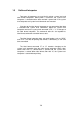
4.5 Increasing and Decreasing Number Printing When continuously increasing and decreasing numbers like serial numbers are to be printed on labels, continuous printing can be performed automatically by the counter in the printer. At this time, the number of steps for increasing and decreasing (addition and subtraction width) and number of prints of the same label can be set.
100 100 100 100 101 98 100 105 102 96 103 10A 103 94 103 10F Fig.3 Fig.4 Fig.1 Fig.
4.6 Sample Printing The print sample and printing data combining the commands above are as follows: [02] m Sets units to metric system [02] M1500 [02] L PK SO D11 Max.
Chapter 5 Interface Functions 5.1 RS-232C Serial Interface 5-2 5.
5.
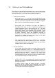
2 XON/XOFF protocol (a) Conditions for sending XON ・ Communication is enabled after power is turned ON. ・ Residual capacity of the buffer is 1 K bytes or more after sending XOFF code. ・ XOFF code is output due to error and printer returns to normal conditions. (b) Conditions for sending XOFF ・ Printer is in error. ・ Printer is in pause state. ・ Received buffer has less than 128 bytes available.
(c) Communication control flowchart The following is a reference flowchart for sending and receiving data by using printer transmission request command (01+A, or 01+F). (In XON/XOFF protocol and compatible machine ON mode) Start Printer status request 01+A or 01+F Command output Reading status from printer Removing error cause/ Clearing pause Paper end Ribbon end, Y Error or pause? Pause, etc.
3 DTR protocol (a) Conditions for making DTR signal Ready (High) The following must be required: ・ Printer is on line. ・ Receive buffer has more than 1K bytes available. Note: When receive buffer has less than 128 bytes available, DTR signal becomes “Busy (Low)” level and this “Busy (Low) level is kept until receive buffer has at least 1 K bytes available. (b) Conditions for making DTR signal BUSY (Low) ・ Printer is in error. ・ Receive buffer has less than 128 bytes available.
5.2 Parallel Interface 1 Specifications Transmission system: 8 bits parallel (compatibility mode) 2 Synchronization: Strobe pulse Handshake: ACKNLG and BUSY Signal logic level: TTL Usable interface connector Printer side: 36-pin amphenol type A standard parallel interface should be used. (The shortest distance should be used for the interface cable.) 3 Connector signal arrangement Pin No.
4 Timing chart min 750ns STROBE max 500ns BUSY 2.5μs (typ.) min min 750ns ACKNLG 750ns DATA ACKNLG "LOW" indicates that the printer has received data. The BUSY "HIGH" indicates that the printer is not able to receive data and the "LOW" indicates that the printer is able to receive data.
Appendixes A.1 List of Commands A-2 A.2 List of Font Character codes A-8 A.3 Printing Edit Function A-10 A.4 Specification of Switching of Control codes A-14 A.5 Specification List of Command sets A-15 A.
Appendix 1 List of Commands Y : Supported command N/A: Not supported command System level commands Models 7106 7206 7010 SOH STX # Reset Y A Printer status transmission request (8 bytes) Y B Pause Y C Stop/cancel Y D Stop immediate execution of system level commands Y E Transmission of number of remaining prints Y F Printer status transmission request [1 byte] Y | Error status transmission request [4-byte] Y A Setting date and time [transmission] a Feedback character transmi
(continued) System level commands Models 7106 7206 7010 STX Mnnnn Setting max.
Commands after the print contents definition mode is turned on with "STX" + "L" None Models 7106 7206 7010 An Set format attribute Y "ESC"+Bn Specifying development method Y Cnnnn Setting column offset Y cnn Setting number of cuts (2-digit) Y Dhv Setting horizontal and vertical pixel sizes Y E Completion of setting printing contents and printing labels Y G Entering previous character column into global register Y Hnn Setting print density (heat factor) Y m Changing units from inc
Font downloading commands Models 7106 7206 7010 ESC *C###D ID assignment Y )S#Wnn..n Descriptor writing Y *C#E Character code writing Y (S#Wnn..
Commands after the print contents definition mode is turned on with "STX" + "L" None Models 7106 7206 7010 An Set format attribute Y "ESC"+Bn Specifying development method Y Cnnnn Setting column offset Y cnn Setting number of cuts (2-digit) Y Dhv Setting horizontal and vertical pixel sizes Y E Completion of setting printing contents and printing labels Y G Entering previous character column into global register Y Hnn Setting print density (heat factor) Y m Changing units from inc
Bar code setting field (after the print contents definition mode is turned on with "STX" + "L") 2nd digit Specified bar code (upper-case characters: visible characters: non-visible code) code, lower-case Models 7106 7206 7010 A Code 3 of 9 Y B UPC-A Y C UPC-E Y D Interleaved 2 of 5 Y E Code 128 Y F EAN-13 G EAN-8 H HIBC (Modulus 43-used Code 3 of 9) Y I CODERBAR Y J Int 2 of 5 (Modulus 10-used Interleaved 2 of 5) Y K Plessey Y L CASE CODE Y M UPC 2DIG ADD (UPC 2-digit
Appendix 2 List of Font Character Codes 1 System font 1 – 6 L H Binary Binary Hex 0000 0 0001 1 0010 2 0011 3 0100 4 0101 5 0110 6 0111 7 1000 8 1001 9 1010 A 1011 B 1100 C 1101 D 1110 E 1111 F 0000 0001 0010 0011 0100 0101 0110 0111 1000 1001 1010 1011 1100 1101 1110 1111 0 1 2 3 4 5 6 7 8 9 A B C D E F (SP) 2 System font 7 (OCR-A) L H Binary 0000 0001 0010 0011 0100 0101 0110 0111 1000 1001 1010 1011 1100 1101 1110 1111 Binary Hex 0000 0 0001
3 System font 8 (OCR-B) H Binary 0000 0001 0010 0011 0100 0101 0110 0111 1000 1001 1010 1011 1100 1101 1110 1111 L Binary Hex 0000 0 0001 1 0010 2 0011 3 0100 4 0101 5 0110 6 0111 7 1000 8 1001 9 1010 A 1011 B 1100 C 1101 D 1110 E 1111 F 0 1 2 3 4 5 6 7 8 9 A B C D E F (SP) 4 Expansion font (CG Triumvirate, CG Triumvirate Bold Smooth font) L H Binary 0000 0001 0010 0011 0100 0101 0110 0111 1000 1001 1010 1011 1100 1101 1110 1111 Binary Hex 0000 0
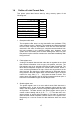
Appendix 3 1 Printing Edit Function Unnaa.. : particular printing contents are changed (see sample No. 1) Printing contents are stored in the field register in order from number 1. The Unnaa.. command replaces the data of "nn" in the field register with "aa.." The transmission data is applied for the changing part and the bit map is regenerated only for the changing part so printing speed is high. 2 s, r : label format storage and readout (see sample No.
Reception buffer * (FIFO) Bit map(printing data) * Unnaa.. Rewrites paticular +pi, -pi contents increment decrement Field register * (stores printing contents) 1 ** raa.. Reads out format On-board SD-RAM G storage Sa s(A/B/C)aa.. Pick up Global register(temporarily) Stores printing contents) * Stores format * ** On-board flash memory * Transmission buffer * (FIFO) * Area sizes such as each buffer and register vary by model.
Sample No. 1 "Unnaa..
1611000000002500002 161100000800250LABEL2 "0002" defined to field No 02 "LABEL2" defined to field No 03 E Ends label format and prints [02] L rfdata D11 Starts label format Reads out file name "fdata" 1611000000002500003 161100000800250LABEL3 E "0003" defined to field No 02 "LABEL3" defined to field No 03 Ends label format and prints Sample No.
Appendix 4 Specification of Switching of Control Codes Control codes can be switched from the menu on the operation panel. By setting to ALT mode, the system level command start code SOH (Immediate execution command) and STX (Sequential execution command) will be changed to the commands in the table below. When setting ALT mode, replace the standard codes in the table below of this command reference with the corresponding codes in ALT mode.
Appendix 5 Specification list of Command set Table below are items whose specifications will be changed using the switching function of the emulation command sets. Relate d comm ands STX O STX f STX Kf STX I STX i STX q STX X STX x s Item DMI/DMW Command sets DM4/DM8 DPP Reference values for printing starting position Reference value for Normal optional positions printing Cutter Peeling Tear off 0220 (2.20inches ) 000 (0.00inches) 0220 (2.20inches ) 220 (2.20inches) 0110 (1.10inches ) 110 (1.
Appendix 6 List of Specifications by Model Table below are specifications required when editing printing for each model such as memory size and the maximum page length.
DASCOM REPRESENTATIVES GERMANY DASCOM Europe GmbH Heuweg 3 D-89079 Ulm Deutschland Tel.: +49 (0) 731 2075 0 Fax: +49 (0) 731 2075 100 www.dascom.com UNITED KINGDOM DASCOM GB Ltd ViewPoint, Basing View, Basingstoke, Hampshire RG21 4RG, England Phone: +44 (0) 1256 481481 Fax: +44 (0) 1256 481400 www.dascom.com RUSSIA and CIS DASCOM Europe GmbH Representation Moscow Leninsky Prospekt 95a, Office 322 119313 Moscow, Russian Federation Phone: +7 (495) 984 70 65 Fax: +7 (495) 984 56 42 www.dascom.