Installation and User Guide 7106 7206 Auto Cutter –1–
© August 2010 DASCOM Europe GmbH –2–
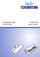
Installation Guide Installing the cutter stand unit (1) Check to make sure that the printer’s power switch is turned off, then disconnect the power cord. (2) Open the top cover. (3) Lift and remove the front cover from the printer. (Keep the removed cover in a safe place, because it is used when the auto cutter has been removed.
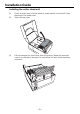
(7) Feed the cable, in 6, so that it lies along the printer’s case. When replacing the connector cover and the motor cover, take care that the covers do not pinch the cable. Cable (8) Set the cutter-stand-unit to the front of the printer with the screw (2) provided.
(4) Remove the screw (1) fastening the motor cover, and then lift and remove the motor cover. Take care that the screw does not fall inside the printer chassis. (5) Remove the screw (1) fastening the optional unit connector cover, and then remove the optional unit connector cover. (6) Plug the connector of the cutter-stand-unit cable into the optional connector on the printer.
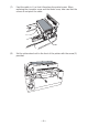
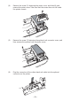
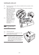
Installing the cutter unit (9) Plug the connector of the cutter-unit cable into the connector on the cutter stand unit. (10) Align the indentations (2) at the bottom of the cutter unit with the protrusions (2) on the cutter stand unit, and then fasten the slotted head screw on the cutter unit with a flat-blade screwdriver. Take care that the cutter unit does not pinch the cable. (11) After the cutter unit is installed, reinstall the motor cover and the optional unit connector cover on the printer.
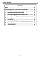
User Guide Contents Notice · · · · · · · · · · · · · · · · · · · · · · · · · · · · · · · · · · · · · · · · · · · · · · · · · · · 8 SAFETY SIGNS that must be strictly observed! · · · · · · · · · · · 10 1. Function· · · · · · · · · · · · · · · · · · · · · · · · · · · · · · · · · · · · · · · · · · · 11 2. Main specifications of auto-cutter · · · · · · · · · · · · · · · · · · 11 3. Checking items inside the accessory box· · · · · · · · · · · · 12 4.
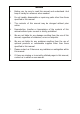
Notice 1. Before use, be sure to read this manual and understand. And keep it handy for reference when needed. 2. Do not handle, disassemble or repair any parts other than those specified in this manual. 3. The contents of this manual may be changed without prior notice. 4. Reproduction, transfer or transmission of the contents of this manual without prior consent is strictly prohibited. 5.
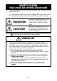
SAFETY SIGNS that must be strictly observed! To prevent personal injury or property damage, the following must be strictly observed. The degree of possible injury and damage due to incorrect use or improperly following instructions specified is described below. WARNING Indicates a situation which, if not observed and handled properly, could result in death or serious injury. CAUTION Indicates a situation which, if not observed and handled properly, could result in personal injury or property damage.
CAUTION Avoid the following conditions to ensure proper operation of the auto-cutter. The cutting blade can be very dangerous. Also, this can cause damage. Room temperature is less than 5°C or more than 40°C. Humidity is less than 30% or more than 80%. Dusty Direct sunlight Chemicals Vibrations or impacts When cutting media (paper) Do not operate auto-cutter without loading paper. This can cause damage to the cutter. Use the standard media (paper). Otherwise, problems such as paper jams may occur.
1. Function The auto-cutter units are designed to cut various media such as labels, tickets and tags precisely and accurately as the setting cut length. 2. Main specifications of auto-cutter Cutting method: Guillotine cutter Maximum cut paper thickness: 0.25 mm (0.01") Minimum cut paper length: 25.4 mm (1") Cut paper width: Maximum: 118 mm (4.65") Minimum: 25.
3. Checking items inside the accessory box Note Auto-cutter is not available for the printer with the peeler. You should check that all of the following items are inside the accessory box. If any are missing, please contact your supplier. Cutter Stand Unit ................................... 1 piece Cutter Unit .............................................. 1 piece Screws .....................................................
4. Auto-cutter settings “Cut On” menu will be selected automatically when the auto-cutter is installed; thus, the printer can be used without adjustment. However, some printers may not have the “AutoConfigure” function. In this case, select the “After Print” menu of the menu setup mode, and the “Cut On” menu on the “Function Select” menu. If the printer has the “AutoConfigure” function, the “AutoConfigure” menu will be printed out in front of “Function Select” menu when you print the “Current Setup”.
CAUTION When a paper jam has occurred, or when the auto cutter has malfunctioned, your supplier or your service representative. Never attempt to repair the auto cutter yourself, it could result in a risk of injury. 5. Cut position The following diagram gives the distance from the media sensor and the thermal printhead to the cutter blade. Printhead position Media cut position Sensor position Cutter blade 24.9mm(0.98") 25.6mm(1.01") 51.5mm(2.
6. Cut settings The auto-cutter-related commands are described below. See the Command Reference manual for more details. The following commands set the cut position and number of operations. Cut-position setup command STX fnnn This command specifies the distance between the sensor and the media cut position. Media-cut command STX o This command executes one media-cut operation.
7. Auto cut-length detection If media with a cut length shorter than the minimum cut length of 25.4mm (1.0 in) is used, the cut media may remain in the cutter unit and cause paper jams. To prevent this, when the printer detects a cut length shorter than the minimum, it feeds the media without operating the cutter. Therefore, use a cut length of 25.4mm (1.0 in) or longer when setting the media cut length. Cutter Printhead Cut prohibition Lc > 25.4mm(1") Minimum cut length: 25.
8. User maintenance If the platen of the printer becomes dirty, the cutter may perform defective cutting even if the auto cutter does not malfunction. Therefore, clean the platen regularly. (See the printer user’s manual) Remove the platen (1) Push the head open lever downwards to open the head unit and sensor arm. (2) Grasp the mounting device of the platen and lift it up as shown in the figure.
9 Troubleshooting If an error is detected, an alarm will sound and an LED on the control panel will display the nature of the error. List of error displays Error Print LED Media Out Off (media location cannot be detected) Condition LED On Off Error LED On Off Auto Cutter Abnormality (such as blade jamming) Off Off On Abnormal auto-cutter temperature On Off Off On Off CAUTION Contact your supplier or service representative, if the following conditions are observed.
– 19 –
DASCOM REPRESENTATIVES GERMANY DASCOM Europe GmbH Heuweg 3 D-89079 Ulm Deutschland Tel.: +49 (0) 731 2075 0 Fax: +49 (0) 731 2075 100 www.dascom.com UNITED KINGDOM DASCOM GB Ltd ViewPoint, Basing View, Basingstoke, Hampshire RG21 4RG, England Phone: +44 (0) 1256 481481 Fax: +44 (0) 1256 481400 www.dascom.com RUSSIA and CIS DASCOM Europe GmbH Representation Moscow Leninsky Prospekt 95a, Office 322 119313 Moscow, Russian Federation Phone: +7 (495) 984 70 65 Fax: +7 (495) 984 56 42 www.dascom.