Installation Guide User Guide 7106 7206 Peeler Unit –1–
© August 2010 DASCOM Europe GmbH –2–
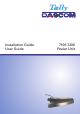
Installation Guide 0 The following installation shows a 7106 printer. The peeler installation for 7206 printers follows the same steps. 1 Before installing the Peeler Unit 1-1 Remove the plastic front cover on the front side of the printer upward as shown below. Be careful that you do not touch other parts when removing the front cover. 1-2 Remove the screw (M3 X 6) of the motor cover and take the motor cover out as shown below.
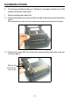
1-3 Remove the screw (M3 X8, for plastic) and take the connector cover out as shown below. Remove the screw and the connector cover 2 Installing the peeler 2-1 While inserting the peeler cable in the space (A) between the paper feed motor and the printer housing, match the protruded pins of the peeler unit to the holes of the front of the mechanism unit. Set the peeler unit to the printer using the accessory screws (3 pcs M3 X 6) enclosed.
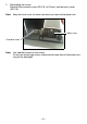
2-2 Connecting the peeler unit cable Connect the peeler unit cable connector to the receptacle of the printer after setting the peeler cable in the printer housing. Note: Set the peeler cable (A) not to touch the print head-up spring (B) of the mechanism unit. It is allowed to set the peeler cable under the paper feed motor instead of the side of the paper feed motor.
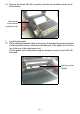
3 Reinstalling the covers Reinstall the connector cover (M3 X 8, for Plastic) and the motor cover (M3 X 6). Note: Keep the front cover for future use which you remove the peeler unit. Motor cover Connector cover Note: Use specified screw for the covers. Do not use wrong type screw, otherwise the screw hole of the printer housing will be damaged.
User Guide Contents Caution ・・・・・・・・・・・・・・・・・・・・・・・・・・・・・・・・・・・・・・・・・・・・・・・・・・・・・ 8 1 Outline ・・・・・・・・・・・・・・・・・・・・・・・・・・・・・・・・・・・・・・・・・・・・・・・・・・ 9 2 Exterior view and part names ・・・・・・・・・・・・・・・・・・・・・・・・・・・・・・・ 9 3 How to operate ・・・・・・・・・・・・・・・・・・・・・・・・・・・・・・・・・・・・・・・・・・・ 10 3-1 Operation ・・・・・・・・・・・・・・・・・・・・・・・・・・・・・・・・・・・・・・・・・・・・ 10 3-1-1 Peeler door opening/closing ・・・・・・・・・・・・・・・・・・・・・ 10 3-1-2 Media loading・・・・・・・・・・・・・・・・・・・・・・・・・・・・・・・・・・ 10 3-1-3 Peeler setting ・・・・・・・・・・・・・・・・・・・・・・・・・・・・・・・・
Caution CAUTION Always use the peeler with the door closed except when the media is loaded into the peeler. Do not push down the door roughly when it is opened, which may cause damage to the hinge of the door. Use the media that meets standard requirements. If not, the liner and label may be jammed in the peeler. Wipe off dirt or glue stuck to the peeler with a soft cloth soaked in a neutral detergent.
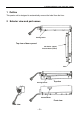
1 Outline/2 Exterior view and part names 1 Outline This peeler unit is designed to automatically remove the label from the liner.
3 How to operate 3-1 Operation 3 How to operate 3-1 Operation 3-1-1 Peeler door opening/closing (1) Opening Shift the release knob of the peeler to the left with the finger, and the peeler door will open. (2) Closing Push down the left end of the peeler door until it clicks closed. 3-1-2 Media loading (1) First peel off the labels with a length of 12cm (5 inch) or more on the top of the loading media, then load the media into the peeler where the first label comes to the peeling sensor.
3 How to operate 3-1 Operation 3-1-4 Initial value of peeling position The paper position for peeling off the label can be adjusted in the printers menu. See an excerpt of the printer menu and the web panel. To adjust the peeling position, designate the feeding amount from the reference point to the peeling position with the command STX f or STX Kf. The value with this command will be effective until the resetting is performed. (For details, see the separate Command Reference.
3 How to operate 3-1 Operation 3-1-5 Peeler commands The following are the peeler commands. For details of each command, see the separate Command Reference. Peeling position designated command STX f, STX Kf This command designates the feeding amount from the reference point to the peeling position. Software switch setting command STX V This command temporarily changes the contents of the option function setting in a nonvolatile memory in the printer.
4 Peeler specifications 4 Peeler specifications Width of liner (a) : 1 − 4.65 in (25.4 − 118 mm) Length of label (b) : 1 − 4.72 in (25.4 − 120 mm) Label: fine media/Thickness: 0.09 mm (including glue layer)/Rolled inwards Minimum width of label (c) : Label must be positioned at 0.63 − 0.87in (16 − 22 mm) from left edge of liner, which is viewed from front of media exit Maximum width of label : To be narrower than liner Thickness of label : 0.0067 in (0.
DASCOM REPRESENTATIVES GERMANY DASCOM Europe GmbH Heuweg 3 D-89079 Ulm Deutschland Tel.: +49 (0) 731 2075 0 Fax: +49 (0) 731 2075 100 www.dascom.com UNITED KINGDOM DASCOM GB Ltd ViewPoint, Basing View, Basingstoke, Hampshire RG21 4RG, England Phone: +44 (0) 1256 481481 Fax: +44 (0) 1256 481400 www.dascom.com RUSSIA and CIS DASCOM Europe GmbH Representation Moscow Leninsky Prospekt 95a, Office 322 119313 Moscow, Russian Federation Phone: +7 (495) 984 70 65 Fax: +7 (495) 984 56 42 www.dascom.