User guide LA48N LA48W Matrix printer
TRADEMARK ACKNOWLEDGEMENTS • Centronics is a trademark of Centronics Data Computer Corporation. • IBM and IBM PC are trademarks of International Business Machines Corporation. • Microsoft, Windows, Windows 95, Windows 98, Windows ME, Windows 2000, Windows 2003 Server, Windows XP and Windows Vista are registered trademarks of Microsoft Corporation. • PostScript is a trademark of Adobe Systems Inc.
Table of contents Table of contents 1 2 Introduction 1-1 Features 1-1 Consumables 1-2 Setting up the printer 2-1 Selecting a location 2-1 Unpacking the printer 2-2 Assembling the printer Installing the Cut Sheet Stand 2-4 2-4 Installing the Ribbon Cartridge 2-5 Getting acquainted with your printer 2-8 Connecting the power cord 2-9 Connecting the printer to your computer Selecting a Parallel Interface Cable 2-11 2-11 Selecting a Serial Interface Cable 2-11 Selecting a USB Cable 2-
Table of contents 3 Paper Handling 3-1 Selecting Paper 3-2 Paper Specifications 3-2 Paper Size 3-2 Paper Thickness and Number of Copies 3-2 Overview of Paper Operations Levers and Buttons Used for Paper Handling 3-3 3-4 Adjusting for Paper Thickness Paper Thickness Lever Positions 3-6 3-7 Using Single Sheets Loading a Single Sheet of Paper 3-8 3-8 Ejecting Single Sheets 3-10 Using Continuous Forms Positioning the Paper Stack Good placement Bad placement 3-11 3-11 3-11 3-11 Loading Continuous F
Table of contents Switching from Single Sheets to Continuous Forms (Push-Feed Mode) 3-22 Tips on Paper Handling General Tips 4 Multipart Forms 3-23 Envelopes 3-23 Labels 3-23 Printing 4-1 Selecting Print Features 4-1 Using Commercial Software 4-1 Using the Control Panel Macrol selection Macro 1 and Macro 2 Settings Installation Settings Adjustments Settings Menu Access Settings Changing the Protocol 4-2 4-2 4-3 4-5 4-5 4-5 4-6 Starting or Stopping Printing Starting Printing 4-8 4-8 Stoppi
Table of contents Overview of the Set-Up Mode Set-Up Mode Functions Example: Changing the Vertical Pitch 5-4 5-4 5-5 Options with Undetermined Values 5-7 Range Management for a Wide Range of Values 5-7 Example: Changing the Left Margin 5-7 Options with Both Pre-determined and Undetermined Values Points to Remember 5-11 Printing the Printer Configuration 5-12 Deciding Which Options to Change Required Options 5-14 5-14 Changing Macro 1 and Macro 2 Options Macro 1 and Macro 2 Options and Values 5-16
Table of contents 7 Replacing the ribbon 6-3 Replacing the Print Head 6-7 Trouble-Shooting Solving Problems Print Quality Problems A B 7-1 7-1 7-1 Paper Handling Problems and Solutions 7-4 Operating Problems and Solutions 7-6 Printer Failures 7-7 Diagnostic Functions 7-8 Checking Vertical Alignment 7-8 Supplies A-1 Supplies A-1 Printer and Paper Specifications B-1 Physical Specifications B-1 Functional Specifications B-2 Performance Specifications Certification B-4 B-4 Paper S
Table of contents C Command Sets DEC PPL2 Quick Reference Guide D E C-1 C-2 IBM Proprinter X24E and XL24E Quick Reference Guide C-22 Epson ESC/P2 Quick Reference Guide C-27 Interface Information D-1 Parallel Interface D-1 Serial Interface D-4 USB Interface D-7 Character Sets E-1 DEC PPL2 Protocol E-1 Common to IBM Proprinter X24 and XL24E Protocol and EpsonESC/P2 Protocol E-19 F VI IBM Proprinter X24E and XL24E Protocol E-25 Epson ESC/P2 Protocol E-26 Resident Fonts F-1
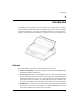
Introduction 1 Introduction Congratulations on purchasing a LA48N/LA48W printer. This printer is a compact, versatile printer that offers maximum compatibility with today’s software packages and personal computers. The 24-wire print head provides crisp, clear printing for business, office, and home environments. This printer is also easy to install and use. Matrix Printer LA48N Features Key printer features and options are listed in the next two sections. Software compatibility.
Introduction High-speed printing. At 10 cpi, print speed ranges from 113 cps for letter quality to 400 cps (80-column printer) or 448cps (136-column printer) for high-speed draft quality. Large print buffer. 64 Kbytes are available in total for storing input data and downloading fonts. A large input data buffer allows you to send files to the printer and return quickly to work in your application. A large download buffer allows you to use custom fonts. 80-column or 136-column print line.
Setting up the printer 2 Setting up the printer Your new printer is easy to install and set up. This chapter tells you how to set up the printerand start printing right away. If this is your first printer, you should read the entire chapter before attempting to use the printer.
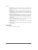
Setting up the printer Unpacking the printer Unpack the printer as follows: 1. Open the carton and remove the printer and its components. Make sure that you have all of the items shown below. Note that the power cord supplied depends on the printer model (100-120 or 220-240 VAC power supply). Q uic k ta S rt e uid G Quick Start Guide and CD-ROM Power cord N 48 LA W 48 A /L CD the on ct file dire F the. or id n tPD res tio oba atu to avoula Acr t.
Setting up the printer head carriage in place (shown below). Front cover Cardboard Removing the shipping restraint cardboard 5. Store the original shipping carton and packaging materials for future use. For example, the original packaging is ideal for use when you move or ship your printer to another location. NOTE: The interface cable is not included with the printer. You must purchase it separately. Connection of the interface cable is described later in this chapter.
Setting up the printer Assembling the printer This section explains how to install the cut sheet stand and ribbon cartridge. Installing the Cut Sheet Stand The cut sheet stand enables smooth feeding of both single sheets and continu-ous forms. Install the cut sheet stand as described below: 1. Referring to the following figure, locate the two grooved notches on the top of the printer, behind the top cover. Note that each notch has a front groove and a rear groove. 2.
Setting up the printer Installing the Ribbon Cartridge The printer uses a black ribbon cartridge. To install the ribbon cartridge: 1. Turn the printer off. Open the front cover of the printer. For easy installation, slide the print head carriage to the middle. 2. The paper thickness lever, located on the right of the printer, has nine positions. Before you install the ribbon cartridge, move this lever to D. Paper thickness lever Move to D.
Setting up the printer 3. Using the procedure below, release the roller from the LOCK position and turn the ribbon feed knob clockwise to take up any ribbon slack. Push in the gray ribbon release tabs on the side of the ribbon cartridge to release them, and slide the roller from the LOCK position to the FREE position. Ribbon feed knob Turn the knob clockwise Roller Release tabs Preparing the ribbon cartridge CAUTION: Do not turn the ribbon feed knob in counterclockwise direction. 4.
Setting up the printer 7. Align the print head position with the dot mark (green) on the printer ejection cover. Dot mark (green) WARNING: Avoid touching the print head while using or immediately after using the printer, as doing so may lead to burns. Wait until the print head cools down before touching it. 8. Thread the ribbon between the print head and the print guide, then gently press down on the ribbon cartridge against the printer until it clicks into place.
Setting up the printer Getting acquainted with your printer Now that your printer is assembled, take a moment to become familiar with its major parts. Looking at the printer from the front right side, you can see the parts of the printer shown in the figure below.
Setting up the printer Looking at the printer from the back with the cut sheet stand and back cover removed, you can see the following parts of the printer: Ejection cover Paper guide Back cover Power connector Interface connector Forms tractors Paper select lever Printer components (rear) Connecting the power cord Before you plug in the printer: 3 Make sure that the printer power is switched off. The side marked “1” on the power switch should be raised.
Setting up the printer 2. Plug the other end of the power cord into the power outlet. Connecting the power cord 3. Make sure that the power cord is securely connected. 4. Turn on the power by pressing the side marked “I” on the power switch. Within a few seconds, the POWER indicator on the printer control panel will light, the print head will move to its home position, and the ONLINE indicator will light (green).
Setting up the printer Connecting the printer to your computer Your printer supports one of the following interface options: Centronics parallel interface only Centronics parallel interface and RS-232C serial interface Centronics parallel interface and USB interface The RS-232 serial interface is a factory-installed option for a Centronics parallel interface model.
Setting up the printer Selecting a USB Cable 3 When the USB interface is used to connect to the host computer, the parallel interface and the serial interface (factory add-on option) cannot be connected simultaneously. 3 The USB interface does not guarantee all connections of USB-supported devices. Connecting the Interface Cable To connect the interface cable: 1. Turn off both the printer and the computer. 2. Pull the shutter on the left side of the printer upward as far as it will go.
Setting up the printer 4. To secure a parallel interface cable, flip the fastener clips located on the printer into the notches on the cable connector. To secure a serial interface cable, tighten the screws in the cable connector. 5. Attach the other end of the interface cable to your computer. Gently pull on the cable to verify that it is secure. 6. Close the shutter. NOTE: When use of the shutter is not required, remove it by using the following pro- cedure.
Setting up the printer Removing the shutter 1. Open the shutter. 2. Gently push the back end of the shutter toward the front of the printer. Shutter 3. While holding the shutter in the position described in step 2, rotate it in the manner shown in the Attaching the shutter Mounting slots Tabs (a) Shutter 5. Tilt the shutter and pass the shutter tabs through the mounting slots, starting with the slot on side (a) shown in the figure on the left.
Setting up the printer Selecting an emulation Before printing with your software, verify that the correct emulation is selected on your printer. This section describes the available emulations and their selection. An emulation is a set of commands used by your software to communicate with the printer. There are many different emulations available for printers. Each emulation has unique features and capabilities.
Setting up the printer To select an emulation, proceed as follows: 1. Switch off the printer. 2. Make sure that paper is loaded (continuous paper or single form). 3. Remove the acoustic cover in order to see the printed text. 4. Hold the Setup/Quit buttons depressed and switch the printer on.
Setting up the printer The initial printout contains a header, help menu 1, and menu 2. The header tells you that the printer is in the Set-Up mode. The help menu provides a quick summary of how to use buttons in the Set-Up mode. The menu 2 lists all of the functions available in the Set-Up mode. Generally speaking, the red cursor 3 on the plastic print guide 4 indicates the function or value to be selected.
Setting up the printer Operations of the control panel This section summarizes status indications and operations of the control panel in Normal mode. For details on Set-Up mode, see Chapter 5, “Using Set-Up Mode”. Normal mode operation includes everyday operations, such as paper handling, macro selection, and protocol selection. The first table lists basic states represented by the Ready and Fault indicators. The second table lists Normal mode operations and required user response.
Setting up the printer Indicator Status Printer status Fault On The printer is out of paper. Blinking fast It is blinking at a 0.5 second period when paper jam, carriage error, communication error, buffer overflow is detected, or when the Automatic Sheet Feeder must be active but paper can not be ejected after 22 inches feeding, or when parking is not successful after 20 inches reverse feeding.
Setting up the printer Control Panel Operations —: This operation has no connection with this condition. N/A: The condition does not apply because this operation is executed before poweringon. Required Conditions1 Operation Printing2 — Not printing On Press FF/Load. Load single sheet paper — Not printing On Press FF/Load if single sheetload is switched from AUTOto MANUAL in Set-Up mode. Feed paper a page — Not printing Off Press FF/Load. Feed paper a line — Not printing Off Press LF.
Setting up the printer Required Conditions1 Operation Required Action Ready Printing2 Resume printing after paper-out Off Not printing On Load paper. Place printer in Ready state Off Not printing Off Press Pause. Place printer in pause state On — Off Press Pause. Enter Normal mode N/A N/A N/A Turn power on without pressing any buttons Continuous Test Print N/A N/A N/A Turn power on while pressing FF/Load. Off Press Protocol(M1) and Park(M2). Press M1 Press M2.
Setting up the printer Required Conditions1 Operation Required Action Ready Printing2 Off Not printing Off Press Exit/Save. Quit Set-Up mode Off without saving values Not printing Off Press Set-Up/Quit. Select a Set-Up Value and move cursor to SAVE&EXIT Fault Clear software-detected errors — — Blink- Press Pause. ing Initialize the printer — — — Turn power off and on again.
Paper Handling 3 Paper Handling This chapter explains how your printer uses paper. Topics covered are: Selecting paper Overview of paper operations Adjusting for paper thickness Using single sheets Using continuous forms (push-tractor feed and pull-tractor feed) Feeding and positioning paper Switching paper types Tips for paper handling are given at the end of this chapter. Check that section if you are using multipart forms, envelopes, or labels.
Paper Handling Selecting Paper The printer can handle either single sheets or continuous forms. Single sheets, also called cut sheets, include envelopes and noncontinuous, multipart forms. Continuous forms include labels and multipart forms fed into the printer using the forms tractors. For best results, use paper that meets the specifications listed in the following table. (See Appendix B, “Printer and Paper Specifications” for detailed specifications.
Paper Handling Overview of Paper Operations The following levers and buttons are used in paper handling: Paper select lever 1 at the top left corner of the printer Paper thickness lever 2 at the top right corner of the printer All buttons 5 on the control panel 3 (Primary and alternative functions are labelled respectively above and under each button.
Paper Handling The following table summarizes the use of levers and buttons in paper handling. More detailed information is provided later in this chapter. CAUTION: To load or feed paper, the printer must be: – In the Ready state but not receiving or printing data – In the Pause state Levers and Buttons Used for Paper Handling Lever/Button Purpose Action FF/LOAD Form feed Press FF/Load to execute a form feed. Continuous forms are fed forward by one page. Single sheets are ejected.
Paper Handling Lever/Button Purpose Action Pause Advance forms to the tear bar when forms are at the Top-of-Form (TOF) position. Press Pause to advance the forms perforation to the tear bar. Tear off the forms, then press Pause again to return theforms to the previous position. Paper select lever* Select paper path Move the paper select lever forward for single sheets. Move the paper select lever backward for continuous forms.
Paper Handling Adjusting for Paper Thickness The printer can handle paper with different thicknesses, including multipart forms with up to five parts (original plus four copies). For details on paper thickness specifications, see Appendix B, “Printer and Paper Specifications”. The paper thickness lever, located at the top right corner of the printer, allows you to adjust for different paper thicknesses. Be sure to adjust the paper thickness lever whenever you change the number of copies being printed.
Paper Handling Paper Thickness Lever Positions Number of Copies (Including the Original) Position 1 copy 1 2 copies 2 3 copies 3 4 copies 4 5 copies 5 Ribbon replacement D For carbon-interleaved paper, the carbon counts as one copy. Vary the position upward or downward (including A to D) to optimize printing. Select D when replacing a ribbon or clearing a paper jam. For labels and envelopes, use the trial-and-error approachto determine a satisfactory position.
Paper Handling Using Single Sheets This section describes how to load paper in the cut sheet stand. The cut sheet stand allows paper to be loaded manually, one sheet at a time. Loading a Single Sheet of Paper To load a sheet of paper into the cut sheet stand: 1. Make sure that the printer is turned on. Check that rear-fed continuous forms are retracted to the park position. (For details, see the section “Unloading Continuous Forms” later in this chapter.) 2. If necessary, reset the paper thickness lever.
Paper Handling 5. Adjust the right paper guide to the width of paper. Insert the paper into the cut sheet stand. Make sure that the bottom edge of the paper engages snugly with the platen. Thepaper will automatically advance to the top-of-form position if the Single Sheet Load option of the Set-Up mode is set to Automatic. NOTE: The factory setting for the Single Sheet Load option is automatic loading, two seconds after paper detection.
Paper Handling 7. Place the printer in the Ready state. Print a sample page and check the page mar- gins. Make the following adjustments, as necessary: Horizontal alignment. Readjust the paper guides if required. Top-of-form setting. Use the printer Set-Up mode (see Chapter 5, “Using Set-Up Mode”) or the TOF Adjustment mode (see the section “Feeding and Positioning Paper” later in this chapter). Margin settings. Use your software or the printer Set-Up mode (see Chapter 5, “Using Set-Up Mode”).
Paper Handling Using Continuous Forms Continuous forms paper, fanfolded at the horizontal perforations, is ideal for printing rough drafts and long files. The paper is fed into the printer using the forms tractors. The forms tractors unit at the rear of the printer pushes paper from the rear to the platen. This is called push-tractor feeding. Positioning the Paper Stack Place the stack of continuous forms paper directly below the rear of the printer.
Paper Handling Loading Continuous Forms This section explains how to use continuous forms. The tractor unit pushes continuous forms. To load continuous forms paper: 1. Make sure that the printer is turned on. Remove any single-sheet paper from the printer. 2. If necessary, readjust the paper thickness lever for continuous forms. (See the section “Adjusting for Paper Thickness” earlier in this chapter.) Paper thickness lever No.
Paper Handling 5. Position the right tractor (as seen from the rear of the printer). Push the right locking lever down to secure the tractor. Center the middle forms support. Cut sheet stand Forms tractors Continuous forms side Locking levers Tractor guide Paper select lever Positioning the tractors Adjusting the left margin Below the right tractor, as seen from the back, there is a tractor guide, short inchbased ruler graduated in 10 columns per inch. Use the ruler to help position the tractor.
Paper Handling 8. Strongly pull the back cover off of the cut sheet stand (in the direction indicated by the arrow) and set it down. Cut sheet stand Back cover Setting the back cover 9. Install the cut sheet stand. For installation, see the section “Installing the Cut Sheet Stand” in Chapter 2. 10. Press the FF/Load button to advance the paper to the top-of-form position. Top-of-form is the first line on which printing can start. 11. Press the ONLINE button to place the printer online.
Paper Handling NOTE: When you use continuous forms, make sure that the edges of both left and right paper guides do not touch the paper. Slide both paper guides flush against the ends of both sides. Good Unacceptable Continuous form Left paper guide Cut sheet stand Right paper guide Adjustment of the paper guides Adjusting the Tear-off position When the FF/Load button is used to advance the paper to cut it, the paper cut position and the perforation position may not match.
Paper Handling Unloading Continuous Forms To unload continuous forms: 1. Make sure that the paper select lever is set to the rear position. 2. Press the Park button. The continuous forms paper is retracted to the park posi- tion. If the paper cannot be retracted in one operation, continue to press the Park button until the paper is parked. NOTE: The printer can retract continuous forms paper a maximum of 55.8 cm (22 inches) per operation. 3.
Paper Handling Tearing Off Continuous Forms Your printer has a special “tear-off edge” that allows you to tear off printed pages without wasting paper. The tear-off edge is located on the ejection cover. To tear off continuous forms using the tear-off edge: 1. Press the FF/Load button. The bottom perforation of the last page advances to the tear-off edge.
Paper Handling Feeding and Positioning Paper Print Area Definition TOF (Top-of-Form): This value defines the distance between the edge of the paper and the place where you allow the printing to begin (position of line number 1). You can adjust this distance according to the condition of your paper (for example, pre-printed forms). When you load the paper, the printer feeds the paper to this position, waiting for printing commands.
... 1 2 3 4 5 6 Paper Handling TOF ABCDEFGHIJ ··· ABCDEFGHIJ ··· ... 1 2 3 4 5 6 7 8 ... L 48 49 50 51 52 ABCDEFGHIJ ··· TOF ...
Paper Handling Line Feed/Form Feed Use the line feed/form feed function to move paper forward. This function is valid whenever the printer is not receiving or printing data and has no fault. Pressing the LF button advances the paper one line. Pressing the FF/Load button feeds one sheet of paper. Except using the Park button for unloading paper or using the Top-of-Form Adjustment mode for fine-adjusting the Top-of-Form position, you are not allowed to execute “reverse” feed from the control panel.
Paper Handling 3. Adjust the Top-of-Form value: To increase the Top-of-Form value of a 1/60 inch, press the per moves forward. To decrease the Top-of-Form value of a 1/60 inch, press the per moves backward. button.The pabutton.The pa- To reset the Top-of-Form value to 0, press the Top button. The paper moves to the edge of the page (position 0). NOTE: If you reach the limit of the permitted range, the printer beeps, and the paper stops moving. 4.
Paper Handling Switching Paper Types If you have more than one type of job, it is often necessary to switch between continuous forms and single sheets. This section explains how to switch between paper types. It is not necessary to remove the continuous forms paper from the printer. CAUTION: This function is not available for continuous forms paper that is fed by the pull-tractor. Switching from Continuous Forms to Single Sheets (Push-Feed Mode) To switch from continuous forms to single sheets: 1.
Paper Handling Tips on Paper Handling General Tips Use high-quality paper. Do not use paper that is wrinkled or curled at the edges. Do not use paper with staples or metal parts. Do not use paper with unpredictable variations in thickness, such as paper with partial multilayers, paper with embossed printing, or labels with the backing sheet exposed. Store paper in a clean, dry environment. Multipart Forms Avoid using carbon-interleaved single sheets if possible.
Paper Handling Test-print labels before running a job. If jams occur, set the paper thickness lever to a wider position. If jamming problems continue, try a different type of label.
Printing 4 Printing This chapter describes the following typical printing operations: Selecting print features Starting, stopping, or resuming printing and viewing last printed lines Removing printed pages Selecting Print Features The print features you select determine how your printer interprets commands from the computer and how your printed pages will look.
Printing Using the Control Panel This printer can directly select some print features from the control panel. These features, listed on the control panel, are two predetermined sets (macros) of print features and three protocols. Use the following procedures to select Macros and Protocols: Macrol selection 1. Press the Protocol M1 and the Park M2 buttons simultaneously to enter Macro selection mode. The M1/M2 indicator starts blinking. 2.
Printing Macro 1 and Macro 2 Settings When you switch from one macro to another, each modification you made using the control panel for the Top-of-Form option or the Protocol option is lost, and the values of these options stored in the new macro become active. The following tables list default values of options for print features. The former is for options in Macro 1 and Macro 2 and the latter is for options independent of Macro selection.
Printing Print Feature Epson defaults Epson national character set Factory Settings Macro 1 Macro 2 USA USA 1 When you change the Macro selection and the new Top-of-Form value is different from the former, paper is automatically fed to the next page, using the new Top-of-Form value. 2 When you change the Macro selection and the paper source selection is different, the printer automatically parks the continuous forms (in Push-Feed mode only) or ejects the cut sheet.
Printing Installation Settings Print Feature Factory Settings Language Tear Single sheet loading Error beep English Auto, 1 second Auto, 2 second One Buffer 64 Kbytes Interface type Auto interface switch time Baud rate Bits and parity Buffer control Disconnected on fault Area control Gather control Tear off control Skip control Automatic sense 2 seconds 9600 bps 8 bits and none XON/XOFF No No No Speed Yes Adjustments Settings Print Feature Factory Settings Fanfold adjust (continuous forms) Manual
Printing Changing the Protocol When you first turn the printer on, the active protocol depends on what port will be used for printing. For Macro 1: If you use the serial port, the active protocol will be the DEC protocol. If you use the parallel port, the active protocol will be the Epson protocol. If you use the USB port, the active protocol will be the Epson protocol. For Macro 2: If you use the serial port, the active protocol will be the DEC protocol.
Printing Indicator Status Active Protocol DEC lit DEC ANSI protocol is active PPX24 lit IBM Proprinter X24E/XL24E protocol is active Both indicatorts lit Epson ESC/P2 protocol is active Flashing alternately According to Set-Up settings, the printer waits for data to switch to a proper protocol.
Printing Starting or Stopping Printing Starting Printing Before you start to print, make sure that paper is loaded. Also, verify that the paper thickness lever is set to the appropriate position (1 to D). To start printing, make sure that the Ready indicator is lit (the printer is ready). If not so, press the Pause button to place the printer in the Ready state. Then start your software. Stopping and Viewing Printing To stop printing, press the Pause button to place the printer in the Pause state.
Printing CAUTION: For continuous forms paper, the page where printing stopped and the page where printing resumes may be incorrectly printed. In this case, wait for the entire job to finish printing. Then reprint the incorrect pages.
Printing Removing Printed Pages This section describes the best methods for removing single sheets or continuous forms paper after printing. Removing Single Sheets When you print using software, the printer automatically ejects each sheet of paper when the end of the printed page is reached. To eject sheets manually: Press the FF/Load button to execute a form feed. Removing Continuous Forms To avoid wasting paper when removing printed continuous forms paper, use the printer's tear-off function.
Using Set-Up Mode 5 Using Set-Up Mode Your Printer has two operation modes: The Normal mode is used for daily operations like paper handling and printing as explained in Chapter 3, “Paper Handling” and Chapter 4 “Printing”. The Set-Up mode is used to change the printer settings that affect the daily operations.
Using Set-Up Mode How Set-Up Works The Set-Up mode consists of Set-Up functions which correspond to the printer settings described in the previous page. Each function generally has many options which correspond to the print features to be changed. Each option includes many parameters values to be selected. All the Set-Up functions, options, and values are printed in a logical sequence on the paper when you enter the Set-Up mode, including the usage of buttons.
Using Set-Up Mode 5. When the printer enters the Set-Up mode, it prints the following information. During the Set-Up mode, the M1/M2 indicator flashes. 1 2 4 MACRO 1 3 Initial printout in setup mode The initial printout contains a header, help menu 1, and menu 2. The header tells you that the printer is in the Set-Up mode. The help menu provides a quick summary of how to use buttons in the Set-Up mode. The menu 2 lists all of the functions available in the Set-Up mode.
Using Set-Up Mode Overview of the Set-Up Mode When you enter the Set-Up mode, the following menu is printed: MACRO 1 MACRO 2 PRINT INSTALL ADJUST TESTS RCALL-FACT MENU-ACCESS SAVE&EXIT The following table summarizes the purpose of each function.
Using Set-Up Mode 3. After selecting the desired values, press the Exit/Save button to reprint the menu where the red cursor is positioned beneath SAVE&EXIT. For each option, the bolded value is the current default value (the value currently savedin the printer’s permanent memory). In the previous example, the default values are PORT DEPND (Port Dependent) for protocol selection and DRAFT (Draft) for font selection.
Using Set-Up Mode 6. Exit the Set-Up mode, saving or not saving the new vertical pitch. button or the button to save 8 lines per inch as the new power-on Press the default in Macro 2, and then exit Macro 2. The printer exits the Set-Up mode and returns to the Ready state. These settings remain in effect until the next time they are changed. Press the Set-Up/Quit button if you do not intend to save these settings in Macro 2.
Using Set-Up Mode Options with Undetermined Values For some options, you can choose among a continuous range of many values. These options are identified as follows: , which means the unit of the range is the Inch. , which means the unit of the range is the Column. , which means the unit of the range is the Line. When you select such an option, only the current value is printed.
Using Set-Up Mode 2. Select the Macro 2 function. button once to position Wait for the printer to stop printing. Then press the the red cursor on the plastic guide of the print head under MACRO 2. Press the button or the button to select the Macro 2 function and print the option and its values. 3. Print the menu of the left margin option. Since you only want to change the left margin, press the button to select the current protocol.
Using Set-Up Mode 1. Select the No of LINE value. A new option menu with undetermined values is printed. 2. Change the value according to the previous procedure. The chart on the next page summarizes how to select options such as protocol and font and how to use the functions that do not have options.
Using Set-Up Mode Enter Set-Up mode: Turn power on with Set-Up/Quit pressed Reprint menu Printer prints menu Select function: Press or to position the cursor, then press or One of the following functions is selected PRINT (list of defaults) and RECALL FACTORY DEFAULTS Press Exit/Save MACRO1, MACRO2, INSTALL, ADJUST, and MENU ACCESS Select values: Press to position cursor, then press or or TESTS (PRINT TEST and HEXDUMP) Select values: Press to position cursor, then press or o
Using Set-Up Mode Points to Remember We recommend that you use continuous forms paper for printing in the Set-Up mode because the output will exceed a single page. To load paper, use the FF/ Load button. To adjust the line position of the paper in the Set-Up mode, use the platen knob. Whenever you enter the Set-Up mode, short help menus are printed at the top of the page. Help menus are also printed when you select the TESTS function. Use the help menus for quick reference while in the Set-Up mode.
Using Set-Up Mode Printing the Printer Configuration The PRINT function prints a list of all the printer’s currently selected values. This function is useful for checking the printer settings when you first enter the Set-Up mode or just before you exit. To print a list of values, first load continuous forms paper, and then enter the Set-Up mode to select the PRINT function. The printer starts to print a list of the currently selected values. The pre-selected factory settings are shown on the next page.
Using Set-Up Mode 5-13
Using Set-Up Mode Deciding Which Options to Change The previous page shows a printout of the printer’s factory settings. In this printout, options are listed by functional group: MACRO 1 and MACRO 2 functions INSTALL function ADJUST function MENU-ACCES function Most selectable values only alter print features such as the type style and page format. Some values must be selected correctly for the printer to work properly with your hardware and software, however.
Using Set-Up Mode Function Option Value ADJUST FNFOLD ADJ MANUAL ADJ You can separately adjust the origin of the Top-of-Form for both continuous forms and single sheets. See the section “Adjusting Top-of-Form Origin” later in this chapter. INSTALL BAUD RATE BIT&PARITY BUFFER CTL DISC FAULT If you have a serial interface, the serial interface options selected on the printer must be the same as the settings you selected using your software or your computer operating system.
Using Set-Up Mode The procedure for changing the MACRO 1 and MACRO 2 options are presented in the previous sections of this chapter. Macro 1 and Macro 2 Options and Values Overprinted values are the factory settings. Some settings are overridden by commands from the computer. Options that differ by protocol are described at the end of the table. Macro1/Macro 2 Values Select the same protocol as that selected by your software.
Using Set-Up Mode Macro1/Macro 2 Values (Protocol Parallel) Description Select a protocol for the parallel interface. This is invalid and skipped when PORT DEPND is not selected for the option. DEC PPL2 DEC PPL2 printers IBM PPX24 – IBM Proprinter X24E printers (LA48N) – IBM Proprinter XL24E printers (LA48W) (Either is selected as factory setting for Macro 2.) EPSON ESCP Epson printers using the ESC/P2 protocol. (Factorysetting for Macro 1.
Using Set-Up Mode Macro1/Macro 2 Values Select a font to be active when the power is turned on. For fixed-spaced fonts, be sure to change the horizontal pitch as well. DRAFT Draft font (lower resolution than letter quality, 3 times the speed of letter quality) HSDRAFT High-impact draft font (lower resolution than lette rquality, 1.
Using Set-Up Mode Macro1/Macro 2 Values
Using Set-Up Mode Macro1/Macro 2 Values Description (Print Direction) UNIDIR Unidirectional printing. Unidirectional printing is used for printing that needs precise vertical alignment. Unidirectional printing is slower than bidirectional printing. BIDIR Bidirectional printing. The printer prints in either direction while seeking the next print direction for a shorter print time. The unidirectional command is ignored. SOFT CNTRL The print direction follows a command from the computer.
Using Set-Up Mode Macro1/Macro 2 Values (Automatic ANSWERBACK) Description Specify whether the ANSWERBACK message is sent to the computer when printer is turned on. NO ANSWERBACK message is not sent. YES ANSWERBACK message is sent. (ANSWERBACK on ENQ) Specify whether the ANSWERBACK message is sent to the computer when printer receives an ENQ code. NO ANSWERBACK message is not sent. YES ANSWERBACK message is sent.
Using Set-Up Mode Macro1/Macro 2 Values Select a character set (language) for the G0.
Using Set-Up Mode Macro1/Macro 2 Values Description Select a character set (language) for the DEC User Preference supplement.
Using Set-Up Mode Macro1/Macro 2 Values Description CP 866 CodePage 866 CP DHN CodePage DHN TURKEY Turkish ECMA 94 ECMA 94 ISO LATIN1 ISO Latin 1 ISO LATIN2 ISO Latin 2 ISO LATIN9 ISO Latin 9 HUNGARY Hungarian SLOVENY Slovenian POLAND Polish MAZOWIA Mazowian KAMENIC Kamenicky CYRILLIC Cyrillic ELOT927 ELOT 927 ELOT928 ELOT 928 LTN POLISH Latin Polish LITHUANY 1 Lithuanian 1 LITHUANY 2 Lithuanian 2 MIK MIK MACEDONIAN Macedonian (IBM Defaults) The foll
Using Set-Up Mode Macro1/Macro 2 Values Description (Epson Defaults) The following are the Set-Up options for the Epson ESC/P2 protocol only. (Epson Character- USA Set) FRANCE Select a national character set.
Using Set-Up Mode Install Options and Values Overprinted values are the factory settings. Install Options Values Specify a language to be used to print the SetUp menu functions and options. ENGLISH English DEUTSCH German ESPANOL Spanish FRANCAIS French ITALIANO Italian Specify the (auto) start timing of tear off feeding.
Using Set-Up Mode Install Options Values Description Enable or disable the printer status buzzer when a fault condition occurs. ONE One beep for a period of about 500 ms CONTINUOUS Buzzer on until the fault condition is cleared OFF Buzzer off under any condition Assign buffer memory as the input buffer.
Using Set-Up Mode Install Options Values Specify the timing of regarding the selected protocol or interface as being inactive when AUTO is specified in the or option.
Using Set-Up Mode Install Options Values Description Setting of data format for the serial interface Number of data bits Parity bit 7 EVEN 7 Even 7 ODD 7 Odd 7 SPACE 7 Space * 7 MARK 7 Mark * 8 EVEN 8 Even 8 ODD 8 Odd 8 NONE 8 None * The mark is logical 1. The space is logical 0. Setting of data transmission buffer control for the serial interface. (Buffer Control) (Disconnect on Fault) DTR The Data Terminal Ready signal is used.
Using Set-Up Mode Adjusting Top-of-Form Origin Print positions often change gradually when you use the printer over long periods of time. The ADJUST function allows you to adjust these positions by fine-tuning the Top-of-Form origin. The following table describes the ADJUST options and values. Options are listed in the order they are printed. Adjust Options and Values Overprinted values are the factory settings.
Using Set-Up Mode Adjust Options Values Description -28/360 Accumlative LF adjustment for Continuous Form -21/360 -14/360 -7/360 0/360 7/360 14/360 21/360 28/360 GRAPHIC -21/360 -14/360 Accumlative LF adjustment for Continuous Form (Last page) -7/360 0/360 7/360 14/360 21/360 GRAPHIC Reserved Changing Menu Access Options You can restrict the access to the Set-Up functions to avoid accidentally changing the Set-Up options.
Using Set-Up Mode Menu Access Option and Values Overprinted values are the factory settings. Menu Access Options Values Description Specify the type of access to the Set-Up functions from the control panel or from the menu. ALL FUNC All functions are accessible. MACRO ONLY Only MACRO 1 and MACRO 2 functions are accessible from the menu. NO ACCESS Set-Up mode is inaccessible. NO PANEL Font, Macro, and Protocol buttons are disabled even in Normal mode.
Using Set-Up Mode Save Settings and Exit Set-up mode This section describes how to exit the Set-Up mode while saving any changes you have made. To exit the Set-Up mode with the settings saved, first select the SAVE&EXIT function and then press the button or the button. Any settings changed while in the Set-Up mode are saved as the new power-on defaults for the printer. The new defaults remain active until you change them again. CAUTION: To temporarily use your changes, press the Set-Up/Quit button.
Using Set-Up Mode Using the Diagnostic Functions The TESTS function allows you to diagnose the printer with the following two functions: PRINT-T (printing test) HEX-DUMP (hex dump) These functions are used for checking print quality and diagnosing printer problems. Hex dump also provides useful information for programmers. There are other options in the TESTS function, but they are restricted to the use of service personnel.
Using Set-Up Mode Hex Dump Mode The Hex Dump mode prints data and commands in hexadecimal characters and abbreviated control codes. The ASCII characters are used for printing. No characters are printed for hexadecimal codes 7F to FF. The Hex Dump mode is useful for checking whether your computer is sending the correct commands to the printer and whether the printer is executing the commands correctly. It is also useful for debugging software programs.
Using Set-Up Mode Sample Hex Dump 5-36
Using Set-Up Mode Set-Up Mode Quick Reference The following flowchart shows how the Set-Up mode is organized. NOTE: Asterisks (*) indicate factory settings. SETUP MODE q MACRO1 MACRO2 PROTOCOL: DEC PPL2 IBM PPX24 EPSON ESCP AUTO PORT DEPND* FORM LENGH: 3 INCHES 3.5 INCHES 4 INCHES 5.5 INCHES 6 INCHES 7 INCHES 8 INCHES 8.
Using Set-Up Mode SETUP MODE FUNCTIONS or OPTIONS&VALUES Move the cursor on the print head. or Select function. or Move the cursor on the print head. Select value, print next option.
Maintenance 6 Maintenance Your printer requires very little care. Occasional cleaning and replacement of the ribbon cartridge are all that is required. Lubrication of the printer is not usually necessary. If the print head carriage does not move smoothly back and forth, clean the printer in the manner described in this chapter. If the problem continues, contact your dealer to determine whether lubrication may be necessary.
Maintenance WARNING: Do not use solvents, kerosene, or abrasive cleaning materials that may damage the printer. 4. Open the front cover of the printer and remove the ribbon cartridge. Using a soft vacuum brush, gently vacuum the platen, print head carriage, and surrounding areas. You can easily slide the print head to the left or right when the power is off. Be careful not to press too hard on the flat ribbon cable that extends from the print head carriage. Flat cable Printer interior 5.
Maintenance Replacing the ribbon To replace the ribbon cartridge: 1. Turn off the printer. 2. Open the front cover of the printer. For easy installation, slide the print head car- riage to a position where it does not face a roller. CAUTION: The print head may be hot if you have been printing recently. 3. Move the paper thickness lever to position D. Paper thickness lever Move to D.
Maintenance 4. To remove the ribbon cartridge, press the ribbon release levers located on either side of the cartridge and carefully lift the cartridge out of the printer. Print head Print guide Removing the ribbon cartridge 5. Using the procedure below, release the roller from the LOCK position and turn the ribbon feed knob clockwise to take up any ribbon slack.
Maintenance 6. Verify that the power to the printer is off. (Make sure that the circle mark on the power switch is pressed.) Printer must be off 7. Move the paper thickness lever to the D position. 8. Open the front cover. 9. Align the print head position with the dot mark (green) on the printer ejection cover. Dot mark (green) Aligning the print head position WARNING: Avoid touching the print head while using or immediately after using the printer, as doing so may lead to burns.
Maintenance 10. Thread the ribbon between the print head and the print guide, then gently press down on the ribbon cartridge against the printer until it clicks into place. (Make sure that the ribbon feed knob is facing upward.) Print guide Print head Ribbon cartridge Ribbon Print guide Tip of print head Installing the ribbon 11. Turn the ribbon feed knob clockwise to take up any ribbon slack. 12. Move the paper thickness lever back to its original position.
Maintenance Replacing the Print Head The print head is easy to replace. CAUTION: The print head may be hot if you have been printing recently. To remove the print head: 1. Turn off the printer. 2. Open the front cover of the printer and remove the ribbon cartridge. 3. Pull the right end of the head lock wire forward to release it from the hook at the right of the print head carriage. Then release the wire from the center hook. 4.
Trouble-Shooting 7 Trouble-Shooting Your printer is extremely reliable, but occasional problems may occur. You can solve many of these problems yourself, using this chapter. If you encounter problems that you cannot resolve, contact your dealer or service for assistance. This chapter is organized as follows: Solving problems Diagnostic functions Getting help Solving Problems The tables in this section describe common printer problems and their solutions.
Trouble-Shooting Problem Solution Printing is too light or too dark. Make sure that the ribbon cartridge is properly installed and that the ribbon feeds smoothly. Make sure that the ribbon cartridge properly installed and that the ribbon feeds smoothly. Make sure that the paper thickness lever is set for the thickness of your paper. See “Paper Thickness Lever Positions” in Chapter 3. Check ribbon wear. Replace the ribbon if necessary. Stains or smudges appear on the page.
Trouble-Shooting Problem Solution Printing is vertically misaligned (jagged). Use the printer's vertical alignment function to check the vertical print alignment. If necessary, adjust the print alignment. See the section “Checking Vertical Alignment” in this chapter. The top margin is wrong. The top margin is the sum of the printer’s top-of-form setting, the software-specified top margin, and the printer’s TOP-MRGN setting. Proceed as follows: Make sure that the top-of-form setting is correct.
Trouble-Shooting Paper Handling Problems and Solutions The following table describes common paper handling problems and suggests solutions. See Chapter 3, “Paper Handling” for detailed procedures on loading and using paper. Problem Solution Paper cannot be loaded or fed. Make sure that the paper select lever located on the top left of the printer is set correctly. Move the lever backward for continuous forms or forward for single sheets. Make sure that the paper covers the paper-out sensor, (i.e.
Trouble-Shooting Problem Solution Paper slips off the forms tractors or the perforated holes of the paper tear during printing. Make sure that the forms tractors are positioned correctly for the width of your paper and that the perforated holes of the paper fit directly over the tractor sprockets. See the section “Using Continuous Forms” in Chapter 3.
Trouble-Shooting Operating Problems and Solutions The following table identifies common operating problems and suggests solutions. If you cannot resolve a problem, contact your dealer or service Problem Solution The power does not turn on. Make sure that the “I” on the printer power switch is depressed. Make sure that the power cord is securely connected to both the printer and the outlet. Make sure that the power outlet is functional. Turn the power off. Wait a minute and then turn the printer on again.
Trouble-Shooting Printer Failures A user cannot generally resolve a problem involving defective printer hardware. On detecting a fatal error, the printer will: Stop printing Beep four times if it is not disabled by the Set-Up mode Turn the Online indicator off Blink the Paper Out indicator (with a fault indicator lit indicating the error type).
Trouble-Shooting Diagnostic Functions The printer diagnostic functions are print-test and hex-dump. Print-test tells you whether the printer hardware is functioning correctly. It prints the print-test pattern. If the printer hardware is functional, any problems you are having are probably caused by incorrect printer settings, incorrect software settings, the interface, or the computer.
Trouble-Shooting NOTE: Do not press any buttons alone or in combination except for pressing the Protocol or the Set-Up/Quit button alone when turning the printer on, to avoid initiating unexpected tests not permitted for the user. 2. Adjust the vertical print alignment at Letter quality speed. Examine the parallel bars. If the bars are aligned (not jagged), go to step 3. If the bars are offset, repeatedly press the button or the button until the bars are aligned. 3.
Trouble-Shooting 4. Exit the vertical alignment function. Press the Exit/Save button to save the new vertical alignment settings and exit the vertical alignment function. NOTE: To exit the vertical alignment function without saving changes, turn the print- er off.
Supplies A Supplies This appendix lists the accessories and options available for the printer. Contact your dealer for information on ordering any of these items.
Printer and Paper Specifications B Printer and Paper Specifications This appendix provides the physical, functional, and performance specifications for the printer. It also contains detailed paper specifications. Physical Specifications LA48N LA48W Dimensions Height Width Depth 120 mm (4.72 inch) 415 mm (16.3 inch) 330 mm (13.0 inch) 120 mm (4.72 inch) 570 mm (22.5 inch) 330 mm (13.0 inch) Weight approximately 7.3 kg (16 lb) 9.7 kg (21.
Printer and Paper Specifications Functional Specifications LA48N Print method Impact dot matrix with a 0.
Printer and Paper Specifications LA48N Character pitch Characters per line 10 cpi 12 cpi 15 cpi 17 cpi 18 cpi 20 cpi LA48W 2.5, 3, 5, 6, 10, 12, 13.2, 15, 16.5, 17, 18 or 20 cpi or proportional spacing. Programmable in 1/360 inch or variousincrements for image graphics. 80 cpl 96 cpl 120 cpl 136.
Printer and Paper Specifications Performance Specifications Print speed Letter Draft High-speed draft 10 cpi 113 cps 360 cps 400 cps (80-column printer) 448 cps (136-colmun printer) Line feed speed 80 ms per line at 6 lines per inch Form feed speed 5.6 inches per second Ribbon life Up to 5.0 million characters 12 cpi 135 cps 432 cps 480 cps (80-column printer) 537 cps (136-colmun printer) Certification B-4 Item 100 V Model 200 V Model Safety standard CSA-C22.2 No.
Printer and Paper Specifications Paper Specifications Print Area This section illustrates the recommended print area for single sheets and continuous forms. 102-266.7 mm (4-10.5 in) for 80-column printer 102-420 mm (4-16.5 in) for 136-column printer May be decreased to 4.23 mm (1/6 inch). However, line spacing may be uneven. 25.4 mm (1 inch) H H 76-364 mm (3-14.3 in) for 80-column printer 76-420 mm (3-16.5 in) for 136-column printer May be decreased to 4.23 mm (1/6 inch).
Printer and Paper Specifications 102-266.7 mm (4-10.5 in) for 80-column printer 102-420 mm (4-16.5 in) for 136-column printer 25.4 mm (1 inch) 102 mm (4 inches) or more Print area May be decreased to 4.23 mm (1/6 inch). However, line spacing may be uneven. 25.4 mm (1 inch) Perforation 25.4 mm (1 inch) Approx. 8.5 mm (0.33 inches): Resume printing is allowable to single-part paper only and selectable by setup mode. Print area Print head position when paper end is detected, selectable by setup mode.
Printer and Paper Specifications Paper Thickness Paper thickness is given by the weight of the paper in either grams per square meter (g/m2) or in pounds per bond (lbs/bond). The following table shows the allowable paper thickness for one-part paper or for each sheet of multipart paper. The total thickness must not exceed 0.35 mm (0.014 inch). The weight of carbonless or carbon-backed paper may vary, depending upon the paper manufacturer.
Printer and Paper Specifications Type of Paper Number of Parts Carbon-backed Do not use in high humidity environments.
Command Sets Function Command C Command Sets This appendix describes printer commands and their parameters. This printer has the following three resident command sets (emulations): • DEC PPL2 (DIGITAL ANSI Printer Protocol Level 2) • IBM Proprinter X24E (LA48N) and IBM Proprinter XL24E (LA48W) • Epson ESC/P2 Select the same protocol on the printer and in your software. If your software protocols include DEC PPL2, select DEC PPL2 for optimum performance.
Command Sets DEC PPL2 Quick Reference Guide Function Command This section contains basic information on the DEC PPL2 commands supported in the GENICOM Matrix Printer LA48.
Command Sets Characters used in control functions appear in monospaced type. The following table Function Command explains some of the conventions used. A pair of numbers separated by a slash (/) character indicates Column/Row notation. This notation refers to the location of a character in a standard code table, such as ASCII. Spaces appear between characters in sequences for clarity; they are not part of the format. Space is designated as ‘‘SP’’ when it is part of the format of a command or sequence.
Command Sets Positioning Controls Function C-4 Command Mnemonic Function Command Remarks BS Backspace 0/8 C0 Control Code CR Carriage Return 0/13 C0 Control Code FF Form Feed 0/12 C0 Control Code HT Horizontal Tab 0/9 C0 Control Code LF Line Feed 0/10 C0 Control Code VT Vertical Tab 0/11 C0 Control Code HTS Horizontal Tab Set 8/8 C1 Control Code 7-bit environment : ESC H IND Index 8/4 C1 Control Code 7-bit environment : ESC D NEL Next Line 8/5 C1 Control Code 7-bit
Command Sets Function Mnemonic Function Command Command Remarks HPR Horizontal Position CSI Pn a Relative Pn = number of columns down VPA Vertical Position Absolute CSI Pn d Pn = position to move to VPR Vertical Position Relative CSI Pn e Pn = number of lines down Mnemonic Function Command Remarks DECSLPP CSI Pn t Pn = number of lines per pages DECVPLA Set Vertical Page Length Alignment CSI Pn1 ; Pn2 - u Pn1 = position of the origin from top of form (in 1/720 in.).
Command Sets Type Size and Spacing, Managing Implicit Cursor Motion Function Command 1 Mnemonic Function DECAWM Autowrap Mode CSI ? 7 h CSI ? 7 l Set autowrap mode Reset autowrap mode DECCRNLM Carriage Return CSI ? 40 h /New Line Mode CSI ? 40 l CR acts as New Line CR acts as Carriage Return DECPSP Proportional Spacing Mode CSI ? 27 h CSI ? 27 l Set proportional spacing mode Reset proportional spacing mode DECSHORP Set Horizontal Pitch CSI Ps w Ps = 0: Determined by current font.
Command Sets Font Management and Attribute Selection Command Function Mnemonic Function Command Remarks SGR Select Graphic Rendition Selecting Fonts CSI Ps m Ps = 10 : Courier Ps = 11 : Timeless PS Ps = 12 : Nimbus Sans Ps = 13 : Prestige Ps = 14 : Pica Ps = 15 : Boldface PS Ps = 16 : Courier Ps = 17 : Compressed Ps = 18 : OCR-A Ps = 19 : OCR-B SGR Select Graphic Rendition Selecting Attributes CSI Ps m Ps = 0: Turn off all attributes Ps = 1: Bold on Ps = 3: Slant on Ps = 4: Underline on Ps = 9: S
Command Sets Tabs Function C-8 Command Mnemonic Function Command Remarks DECCAHT Clear All Horizontal Tabs ESC 2 deprecated command DECCAVT Clear All Vertical Tabs ESC 4 deprecated command DECHTS ESC 1 deprecated command DECSHTS Set Horizontal Tab Stops CSI Pn ; . . . ; Pn u Pn = tab stop DECSVTS Set Vertical Tab Stops CSI Pn ; . . . ; Pn v Pn = tab stop DECVTS Vertical Tab Set ESC 3 deprecated command TBC Tab Clear CSI Ps ; . . . ; Ps g Ps = 0: Clear horiz.
Command Sets Selecting Function Character Sets Command See Figure “Designating and Invoking Character Sets” later in this section. Mnemonic Function Command Remarks ASCEF Announce Subset of Code Extension Facilities ESC SP L ASCII in G0 and GL. ISO Latin-1 in G1 and GR. Same as ESC SP L ASCII in G0 and GL. ESC SP M ESC SP N DECAUPSS Assign User Preference Supplemental Set ISO Latin 9 DCS Ps ! u D . . . D ST Ps = 0: 94-char. set Ps = 1: 96-char. set D . . . D: SCS designating sequence.
Command Sets SCS Final Characters Function Character Set Command I2 F Designator Charactors 94-Character Sets C-10 British A 4/1 ASCII B 4/2 DEC Dutch 4 3/4 DEC Finnish 5 3/5 French R 5/2 DEC French-Canadian 9 3/9 German K 4/11 DEC Hebrew Supplemental "4 2/2, 3/4 DEC 7-Bit Hebrew %= 2/5, 3/13 ISO Italian Y 5/9 Legal %4 2/5, 3/4 JIS Katakana I 4/9 JIS Roman J 4/10 DEC Norwegian/Danish 6 3/6 ISO Spanish Z 5/10 DEC Swedish 7 3/7 DEC Swiss = 3/13 Norwegian
Command Sets Function Set Character I2 F Designator Command Charactors 96-Character Sets ISO Latin-1 Supplemental A 4/1 ISO Latin-2 Supplemental B 4/2 ISO Latin-9 Supplemental b 6/2 ISO Latin-Greek Supplemental F 4/6 ISO Latin-Hebrew Supplemental H 4/8 ISO Latin/Cyrillic Supplemental L 4/12 ISO Latin-5 Supplemental M 4/13 User Preference Supplemental < 3/12 Reports Mnemonic Function Command Remarks DA Device Attributes CSI c Request Device Attributes Report DAR Device Att
Command Sets Function Mnemonic C-12 Function Command Remarks Command DECLANS Load ANSWERBACK With Password DCS Ps ; Pn2 ; Pn3 Ps = 1 : No password - Do not store v encoded_message_ message. string ST Ps = 2 : No password - Store message.
Command Sets Miscellaneous Function Mnemonic Function Command Command Remarks BEL DECSCL Bell Select Conformance Level 0/7 CSI Ps1 " p C0 Control Code Ps = 0: reset - native level Ps = 71: reset - DEC PPL1 Ps = 72: reset - DEC PPL2 DECSTR Soft Terminal Reset CSI ! p Reset to initial state RIS Reset to Initial State ESC c Reset to initial state DECIPEM IBM Proprinter Protocol Mode CSI ? 58 h CSI ? 58 l Deprecated function ROCS Return from Other Coding System ESC % @ Return to DEC PPL2 m
Command Sets Barcode Function Printing Mnemonic C-14 Function Command Command Remarks DECBAR Start or Stop Bar ESC % SP 0 Codes ESC % @ Start barcode Stop barcode DECSBCA Select Bar Code Attributes CSI Ps1 ; Pn2 ; . . .
Command Sets Active position after printing a bar code is the same position as before printing bar code. Function Command After printing bar code, appropriate positioning control commands, see “Positioning Controls” earlier in this section, must be sent to print additional barcode strings, text or graphics. In the following examples, HPA Pn command positions the Active Position at column Pn , VPA Pn command positions the Active Position at line Pn. 1.
Command Sets Sixel Graphics Protocol Selector Ps1 Function Command Ps1 Value Horizontal Grid Size (inches) Aspect Ratio (Vert : Hor)1 0, 1 or none 1/144 2 2 1/360 5 3, 4 1/180 2.5 5, 6, 7, 8 1/144 2 9 1/72 1 >9 1/144 2 1 Vertical Grid size = 1/72 in., unless modified by Pn3 or DECGRA. Sixel Graphics Grid Size defined by Pn3 HGS:VGS (dpi) by Aspect Ratio (defined by Ps1) Pn3 Value 1:1 C-16 2:1 2.
Command Sets Sixel Graphics Control Codes Function Mnemonic Function Command Command Remarks DECGRA Set Raster Attributes " (2/2) Defines the pixel aspect ratio. Followed by parameters Pn1 ; Pn2 ; Pn3 ; Pn4 Pn1 : Pixel aspect ratio numerator Pn2 : Pixel aspect ratio denominator Pn3 and Pn4 : ignored DECGRI Graphics Repeat Introducer ! (2/1) Followed by a numeric value Pn and a sixel data to be repeated Pn times.
Command Sets Standard 8-bit Code Table (Left Half) Standard Left C0 Control Set Column Row 0 NUL 1 SOH 2 STX 3 ETX 4 EOT 5 ENQ 6 ACK 7 BEL 8 BS 9 HT 10 LF 11 VT 12 FF 13 CR 14 SO 15 SI 0 0 0 0 1 1 1 2 2 2 3 3 3 4 4 4 5 5 5 6 6 6 7 7 7 10 8 8 11 9 9 12 10 A 13 11 B 14 12 C 15 13 D 16 14 E 17 15 F Graphics Left (GL) 1 DLE DC1 (XON) DC2 DC3 (XOFF) DC4 NAK SYN ETB CAN EM SUB ESC FS GS RS US 2 20 16 10 21 17 11 22 18 12 23 19 13 24 20 14 25 21 15 26 22 16 27 23 17 30 24 18 3
Command Sets Standard 8-bit Code Table (Right Half) Standard Right C1 Control Set 1 2 3 4 5 BPH NBH IND NEL 6 SSA 7 ESA 8 HTS 9 HTJ 10 VTS 11 PLD 12 PLU 13 RI 14 SS2 15 SS3 200 128 80 201 129 81 202 130 82 203 131 83 204 132 84 205 133 85 206 134 86 207 135 87 210 136 88 211 137 89 212 138 8A 213 139 8B 214 140 8C 215 141 8D 216 142 8E 217 143 8F 9 DCS PU1 PU2 STS CCH MW SPA EPA SOS SCI CSI ST OSC PM APC 10 220 144 90 221 145 91 222 146 92 223 147 93 224 148 94 225 149 95 226 150
Command Sets Designating and Invoking Character Sets 1 LS0 2 LS1 GL C0 C1 GR 3 SS2 or LS2 4 LS1R Invoking "Invoking" Sequences Locking Shift, Single Shift, or Announcers 1 2 3 4 5 7 6 5 SS3 or LS3 6 LS2R 7 LS3R G0 G1 G2 G3 "Designating" Sequences (SCS) or Announcers Selecting 94-Char Graphic Repertory 96-Char Graphic Repertory DECAUPSS User Preference Power-up configuration is as follows: GL:G0 GR:G2 G0:Value for DEC G0 CST Set-Up option G1:ASCIIG2:User Preference G3:User Preference
Command Sets National FunctionReplacement Character Sets Command National Replacement Character Sets Location US ASCII British 2/3 # £ 4/0 @ 5/11 [ 5/12 DEC Finnish French DEC FrenchCanada ISO German Italian £ JIS Roman £ à à § § Ä ° â Ä ° \ Ö ç ç Ö ç 5/13 ] Å § ê Ü é 5/14 ^ Ü î 6/0 ‘ é ô 7/11 { ä é é ä à 7/12 | ö ù ù ö ò 7/13 } å è è ü è 7/14 ~ ü ¨ û ß ì ¥ ù — National Replacement Character Sets Location US ASCII DEC Norwegia
Command Sets IBM Proprinter X24E and XL24E Quick Reference Guide Function Command This section describes the printer commands for the IBM Proprinter X24E and XL24E protocol. When there is a difference, it is identified by LA48N (X24E) and LA48W (XL24E). Asterisks in the “Function” column indicate extended commands that are not supported by the original printer.
Command Sets Function Command Horizontal Control Space Backspace Carriage return Elite characters on Proportionally spaced characters on/off (on: n = 1, off: n = 0) SP BS CR ESC : ESC P (n) Vertical Control Line feed Form feed Advance paper n/216 inch (1 ≤ n ≤ 255) Advance paper n/180 inch (in AG mode) (1 ≤ n ≤ 255) Set line spacing to 1/8 lines Set line spacing to 7/72 inch Set line spacing to n/216 inch (0 ≤ n ≤ 255) Set line spacing to n/180 inch (in AG mode) (0 ≤ n ≤ 255) Preset line spacing to n/7
Command Sets Function Command Vertical tab execution Set vertical tabs The values of n1to nk in this command are the ASCII values of the lines (at the current line spacing) at which tabs are to be set. (1 ≤ n ≤ 255) (1 ≤ k ≤ 64) Clear all vertical tabs Reset tabs to default values VT ESC B (n1) ...
Command Sets Function Command Select code page table (0 ≤ n1, n2 ≤ 255) (n = n1 + n2 X 256) c1, c2: Decimal (n1 = 4, n2 = 0) ESC [ T (n1) (n2) 0 0 (c1) (c2) c1 c2 Code page ID 0 0 0 1 3 3 3 3 3 3 3 3 3 3 23 0 210 220 181 82 83 84 89 90 92 94 95 97 98 27 Ignore command Code page 210* Code page 220* Code page 437 Code page 850 Code page 851* Code page 852* Code page 857* Code page 858** Code page 860 Code page 862* Code page 863 Code page 865 Code page 866* ISO 8859-15** Clear input buffer Select p
Command Sets Function Command Cut Sheet Feeder Control* Feed a sheet from bin 1* Feed a sheet from bin 2* Feed a sheet from bin 3* Eject a page from the printer* ESC EM 1 ESC EM 2 ESC EM E ESC EM R Miscellaneous Sound the bell Unidirectional printing on/off (on: n = 1, off: n = 0) Add a carriage return to all line feeds (on: n = 1, off: n = 0) Printer offline Select default settings C-26 BEL ESC U (n) ESC 5 (n) ESC j ESC [ K (n1) (n2) (i) (ID) (p1) (p2)
Command Sets EpsonFunction ESC/P2 Quick Reference Guide Command This section describes the printer commands for the Epson ESC/P2 protocol. Asterisks in the “Function” column indicate extended commands that are not supported by the original printer. See the Programmer’s Reference Manual for detailed information on using these commands.
Command Sets Function Command Select printing style This command allows you to combine various printing styles. The value of n is the sum of the values of the styles you want to combine.
Command Sets Function Command Vertical Control Line feed Form feed Advance paper n/180 inch (1 ≤ n ≤ 255) Set line spacing to 1/8 inch Set line spacing to n/180 inch (0 ≤ n ≤ 255) Set line spacing to n/60 inch (0 ≤ n ≤ 127) Set line spacing to 1/6 inch Set line spacing to n/360 inch (0 ≤ n ≤ 255) LF FF ESC J (n) ESC 0 ESC 3 (n) ESC A (n) ESC 2 ESC + (n) Tabulation Horizontal tab execution Set horizontal tabs The values of n1to nk in this command are the ASCII values of the print columns (at the current
Command Sets Function Page Formatting Set right margin to column n (1 ≤ n ≤ 255) Set left margin to column n (0 ≤ n ≤ 255) Set top and bottom margins from top of page n1 = 4, n2 = 0 • Top margin = (t1 + t2 X 256)/360(*1) inch (0 ≤ t1 ≤ 255) (0 ≤ t2 ≤ 127) • Bottom margin = (b1 + b2 X 256)/360(*1) inch (0 ≤ b1 ≤ 255) (0 ≤ b2 ≤ 127) Set perforation skip by n lines (1 ≤ n ≤ 127) Perforation skip off Set page length to n lines (1 ≤ n ≤ 127) Set page length to n inches (1 ≤ n ≤ 22) Set page length to (d1 + d2
Command Sets Function Command Select international character set ESC R (n) n = 0: USA 1: France 2: Germany 3: United Kingdom 4: Denmark 1 5: Sweden 6: Italy 7: Spanish 1 8: Japan 9: Norway 10: Denmark 2 11: Spanish 2 12: Latin America 13: Korea 64: Legal Assign a character set to active character set ESC ( t (n1) (n2) (d1) (d2) (d3) number 0 to 3, n1 = 3, n2 = 0 d2, d3: Decimal d1 = 0: Active character set number 0, default is Italics 1: Active character set number 1, default is Graphics 2: Active charac
Command Sets Function Command Clear input buffer Delete a character Force most significant bit to 1 Force most significant bit to 0 Cancel control over most significant bit CAN DEL ESC > ESC = ESC # **Code page contains Euro currency symbol Font Selection and Downloading Select font n = 0: Resident character set 1: Downloaded character set Select letter or draft quality n = 0: Draft 1: Letter Select type style • Bitmap font: n = 0: Courier 1: Courier 2: Courier 3: Prestige 4: Courier 5: OCR-B 7: Courie
Command Sets Function • n1 and n2 set point size of font. Point size = (n1 + n2 X 256) X 0.
Command Sets C-34
Interface Information D Interface Information This printer can communicate with a computer through either a RS-232 serial interface or a Centronics parallel interface. The printer can use both interfaces at the same time when the I/F TYPE option is set to AUTO in the Set-Up mode. This appendix provides information you may need for wiring your own interface cables or for programming computer-to-printer communications. Most users do not need the information in this appendix.
Interface Information Centronics Compatible Signals Pin Direction Signal Description 1 To printer STROBE L STROBE pulse low to read data A strobe low signal will raise BUSY line to high. 2 3 4 5 6 7 8 9 To To To To To To To To printer printer printer printer printer printer printer printer DATA BIT 1 DATA BIT 2 DATA BIT 3 DATA BIT 4 DATA BIT 5 DATA BIT 6 DATA BIT 7 DATA BIT 8 These signals are the 1st to the 8th bits of parallel data.
Interface Information Pin Direction Signal Description 33 0 volts. Same as pins 14, 19-30. 34 Not used 35 Not used 36 Not used IEEE 1284-B Nibble Mode signals The following table briefly gives connector pin assignments in IEEE 1284 mode.
Interface Information Pin Direction Signal Description 31 To printer Init L Set to high for Reverse Channel operation 32 From printer DataAvail L Reverse channel: Data 0 and 4 33 Not used 34 Not used 35 Not used 36 To printer SelectIn L Set to high for Reverse Channel Serial Interface Use the Digital BC16E cable or equivalent.
Interface Information Serial Options The serial options for the computer and the printer must match. Use the printer control panel, the computer operating system, or your software to change options specified as “selectable.
Interface Information D-6 Buffer Control Description XON/XOFF (DC1/DC3) When the printer is ready to receive data, it sends the XON (DC1) code (hex 11). When fewer than 255 bytes of space remain in the buffer (or when the printer is taken offline), the printer sends the XOFF (DC3) code (hex 13). (When the input buffer is configured for 256 bytes, the buffer limit is reduced from 255 bytes to 63 bytes.
Interface Information USB Interface Cable This printer supports the USB 1.1 Full speed specification. To connect to the host, use USB 2.0-compliant INF cables (5 meters/196 inch or shorter). Use shielded cables. Connector pin alignment No.
Interface Information D-8
Character Sets E Character Sets This appendix provides character sets available for this printer. Available character sets depend on the protocol selected.
Character Sets • DEC Special Graphics Character Set • DEC Technical Character Set • ISO Latin-1 Supplemental Character Set * • ISO Latin-9 Character Set • Legal Character Set • Hebrew Character Sets – DEC 7-Bit Hebrew Character Set – DEC Hebrew Supplemental Character Set – ISO Latin-Hebrew Supplemental Character Set * • Greek Character Sets – DEC 8-Bit Greek Supplemental Character Set – ISO Latin-Greek Supplemental Character Set * • Turkish Character Sets – DEC 7-Bit Turkish Character Set –
Character Sets E-3
Character Sets E-4
Character Sets E-5
Character Sets E-6
Character Sets E-7
Character Sets E-8
Character Sets E-9
Character Sets E-10
Character Sets E-11
Character Sets E-12
Character Sets E-13
Character Sets E-14
Character Sets E-15
Character Sets E-16
Character Sets E-17
Character Sets E-18
Character Sets Common to IBM Proprinter X24 and XL24E Protocol and Epson ESC/P2 Protocol Default Sets The following thirty two character sets are available.
Character Sets E-20 Code Page 851 Code Page 852 Code Page 857 Code Page 858 Code Page 860 Code Page 862
Character Sets Code Page 863 Code Page 865 Code Page 866 Code Page DHN Turkish ECMA 94 E-21
Character Sets ISO Latin 1 ISO Latin 2 ISO Latin 9 Hungarian Slovenian Polish E-22
Character Sets Mazowian Cyrillic ELOT 928 Kamenicky ELOT 927 Latin Polish E-23
Character Sets Lithuanian 1 Lithuanian 2 MIK Macedonian E-24
Character Sets IBM Proprinter X24E and XL24E Protocol IBM Set 1/2 IBM character set 1 and IBM character set 2 IBM Set 1 IBM Set 2 E-25
Character Sets Epson ESC/P2 Protocol National Character Sets The following fifteen character sets are available. USA, France, Germany, UK, Denmark 1, Sweden, Italy, Spain 1, Japan, Norway, Denmark 2, Spain 2, Latin America, Korea, and Legal Common Characters The following table shows characters common to the fifteen “national” character sets. NR indicates characters that differ with languages.
Character Sets National Characters The following table shows “national” characters that differ with languages. Character codes correspond to NRs in the preceding table.
Resident Fonts F Resident Fonts This appendix provides print samples of the printer’s twelve resident fonts.
Resident Fonts Timeless (outline) Nimbus Sans ® (outline) OCR A OCR B F-2
“All rights reserved. Translations, reprinting or copying by any means of this manual complete or in part or in any different form requires our explicit approval. We reserve the right to make changes to this manual without notice. All care has been taken to en-sure accuracy of information contained in this manual. However, we cannot accept responsibility for any errors or damages resul-ting from errors or inaccuracies of information herein.
TALLY REPRESENTATIVES GERMANY UNITED KINGDOM DASCOM Europe GmbH Heuweg 3 D-89079 Ulm Deutschland Tel.: +49 (0) 731 2075 0 Fax: +49 (0) 731 2075 100 www.dascom.com DASCOM GB Ltd ViewPoint, Basing View, Basingstoke, Hampshire RG21 4RG, England Phone: +44 (0) 1256 481481 Fax: +44 (0) 1256 481400 www.dascom.com SINGAPORE DASCOM AP Pte Ltd 63 Hillview Avenue #08-22, Lam Soon Industrial Building Singapore 669569 Phone: +65 6760 8833 Fax: +65 6760 1066 www.dascom.