User Guide MIP480 Mobile Impact Printer
FCC Compliance Statement This device complies with Part 15 of the FCC Rules. Operation is subject to the following two conditions: (1) This device may not cause harmful interference, and (2) This device must accept any interference received, including interference that may cause undesired operation. Canadian Compliance Statement This digital apparatus is in conformity with standard NMB-003 of Canada. Cet appareil numérique est conforme à la norme NMB-003 du Canada.
Table of Contents Introduction 1-1 Features 1-2 Options 1-2 Paper Handling 2-1 Getting to Know the Printer’s Major Parts and the Control Panel 2-1 Operations of the Control Panel 2-4 Basic States of the Printer 2-4 Selecting Paper 2-7 Paper Specifications Paper Size Paper Thickness and Number of Copies 2-7 2-7 2-7 Overview of Paper Operations Levers and keys used for Paper Handling 2-8 2-9 Adjusting for Paper Thickness 2-10 Using Continuous Forms Positioning the Paper Stack 2-11 2-11
Table of Contents Printing 3-1 Using the Control Panel 3-1 Starting or Stopping Printing Starting Printing Stopping and Viewing Printing Resuming Printing Resuming from a Paper-Out 3-2 3-2 3-2 3-2 3-2 Removing Printed Pages Removing Single Sheets 3-3 3-3 Sleep Mode Entering Sleep Mode Leaving Sleep Mode 3-4 3-4 3-4 Using Special Mode Special Mode Functions Entering Special Mode ii 4-1 4-1 4-2 Set-Up Mode Function How Set-Up Works Entering the Set-Up Mode Overview of the Set-Up Mode Options wit
Table of Contents Maintenance 5-1 Cleaning Cleaning and Vacuuming the Printer Cleaning the Paper Bail Rollers Cleaning the Print Head 5-1 5-1 5-2 5-3 Replacing the Ribbon Cartridge Removing the Ribbon Cartridge Installing the Ribbon 5-4 5-4 5-5 Replacing the Print Head 5-6 Trouble-Shooting 6-1 Solving problems 6-1 Print Quality Problems and Solutions 6-2 Paper Handling Problems and Solutions 6-3 Operating Problems and Solutions 6-4 Printer Failures 6-5 Diagnostic Functions Checking Vert
Table of Contents USB Interface (Universal Serial Bus) Features D-5 D-5 Bluetooth Wireless Interface D-6 IEEE 802.
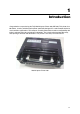
1 Introduction Congratulations on purchasing the Tally Mobile Impact Printer 480 (MIP480). This printer is an 80 column, 24 wire, serial dot matrix printer specifically designed as a robust output device for use in vehicular applications. This compact, versatile printer offers maximum compatibility with today’s software packages and personal computers. The 24-wire print head provides crisp, clear printing of invoices and documents. This printer is also easy to install and use.
Introduction Features Key printer features and options are listed in the next two sections. • Software compatibility. This printer operates with IBM Proprinter XL24E and Epson-EP2 emulations. • Various character sets. For IBM Mode: IBM Set 1 and Set 2. For EPSON Mode: 15 National Character Sets. • Multiple fonts. The printer has thirteen resident fonts: Draft, Roman, Sans Serif, Courier, Bold, Prestige, Script, Orator, Gothic, OCR-A, OCR-B, Sans Serif H and Roman T.
2 Paper Handling This chapter explains how your printer handles paper. Topics covered are: • • • • • • • • Getting to know the printer’s major parts and the control panel Selecting paper Overview of paper operations Adjusting for paper thickness Using single sheets Using continuous forms Feeding and positioning paper Switching paper types Tips for paper handling are given at the end of this chapter. Check that section if you are using multipart forms, invoices, envelopes, or labels.
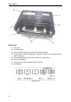
Paper Handling Front View 1 Top Cover 2 Cut Sheet Edge 3 Power Supply Connector (to connect to the vehicle battery) 4 Control Panel (to load and feed paper, select print features, or change the printer’s optional settings) 5 Single Sheet Edge Guides (to adjust location of single sheets) 6 Easy Load Platforms 7 Tractor Doors (to hold and feed continuous forms) 8 Front/Bottom Control Panel 2-2
Paper Handling Front Rear Left Side View 1 Power Switch 2 Cover Latch (to secure top cover) 3 Forms Tractors (to hold and feed continuous forms) 4 Paper Guides (to guide single sheets) 5 Paper Exit Slot and Tear Edge 6 Top Cover – Rear 7 Single Sheet Tray (Shown in down Position) Bottom View 8 Interface Connectors (or Wireless Adapters if installed) Vertical Position Bottom View 2-3
Paper Handling Operations of the Control Panel This section summarizes status indications and operations of the control panel in Normal mode. For details on Set-Up mode, see Chapter 4, “Using Set-Up Mode.” Normal mode operation includes everyday operations, such as paper handling, font selection, macro selection, and protocol selection. The first table lists basic states represented by the Ready and Fault indicators. The second table lists Normal mode operations and required user response.
Paper Handling Operation Required Conditions*1 Required Action Ready Printing*2 Fault Load continuous forms paper — Not printing On Press FF/LOAD. Load single sheet paper — Not printing On Paper is automatically detected and advanced (autoloading) when it is first inserted. In this mode, if the FF key is pushed, the inserted sheet will be ejected from the printer and the Fault LED will light, indicating paper out condition. Feed paper a page — Not printing Off Press FF/LOAD.
Paper Handling Operation Required Conditions*1 Required Action Ready Printing*2 Fault Enter Set-Up mode N/A N/A N/A Turn power on while pressing SETUP/EXIT. Move cursor to select a Set-Up Function or Value Off Not printing Off Press NEXT or PREVIOUS key. Move cursor to select a Set-Up Option Off Not printing Off Press NEXT or PREVIOUS key. Select a Set-Up Function or Value Off Not printing Off Press ALT-NEXT or ALTPREVIOUS key.
Paper Handling Selecting Paper The printer can handle either single sheets or continuous forms. Single sheets, also called cut sheets, include envelopes and non-continuous, multipart forms. Continuous forms include labels and multipart forms fed into the printer using the forms tractors. For best results, use paper that meets the specifications listed in the following table. (See Appendix B, “Printer and Paper Specifications,” for detailed specifications.
Paper Handling Overview of Paper Operations The following levers and keys are used in paper handling. Lift the cover to locate these levers inside the printer. • Print Gap lever on the left side under the cover • Paper Select lever on the right side under the cover The following figure shows the location of each lever, indicators, and keys: Print Gap Lever Paper Select Lever • All keys on the control panel for primary and alternative functions are labeled below and above respectively.
Paper Handling The following table summarizes the use of levers and keys in paper handling. More detailed information is provided later in this chapter. CAUTION: To load or feed paper, the printer must be: • In the Ready state but not receiving or printing data • In the Pause state Levers and keys used for Paper Handling Lever/key Purpose Action FF/LOAD Form Feed Press FF/LOAD to execute a form feed. Continuous forms are fed forward by one page. Single sheets are ejected.
Paper Handling Adjusting for Paper Thickness The printer can handle paper with different thicknesses, including multipart forms with up to four parts (original plus three copies). For details on paper thickness specifications, see Appendix B “Printer and Paper Specifications.” The Print Gap lever, located on the left under the cover, allows you to adjust for different paper thicknesses. Be sure to adjust the Print Gap lever whenever you change the number of copies being printed.
Paper Handling Using Continuous Forms Continuous forms paper, fanfolded at the horizontal perforations, is ideal for printing rough drafts, long files, forms and invoices. The paper is fed into the printer using the forms tractor unit. The Push tractor is at the front/bottom of the printer. The paper is loaded and adjusted via keys. The forms may be advanced to tear off position by operator or automatically through a timeout.
Paper Handling Loading Continuous Forms (Push Tractor) This section explains how to use continuous forms with a push tractor at rear (or bottom, depending on printer orientation). Paper is loaded and adjusted via keys. Forms may be advanced to tear off feature by operator or by host. To load continuous forms paper: 1 Make sure that the printer is turned on. Remove any single-sheet paper from the printer. 2 If necessary, readjust the Print Gap lever for continuous forms.
Paper Handling 5 Raise the tractor doors and fit the first two paper feed holes onto the right tractor pins. 6 Holding paper against the Easy-Load Platform, fit the paper into the tractor. Close the tractor Door. Repeat the procedure for the left tractor and adjust the left forms tractor to accommodate the width of the form. 7 Move the left tractor to make the paper flat. Do not stretch the paper too taut. Push the left locking lever down to secure the tractor in place.
Paper Handling Unloading Continuous Forms To unload continuous forms: 1 Make sure that the Paper Select lever is set to the continuous forms position. 2 Press the PARK key. The continuous forms paper is retracted to the park position. If the paper cannot be retracted in one operation, continue to press the PARK key until the paper is parked. NOTE: The printer can retract continuous forms-paper by a recommended maximum of 25.
Paper Handling 2 Tear the paper off at the perforation by pulling the paper to the rear, against the tear edge.
Paper Handling Using Single Sheets This section describes how to load paper in the Single Sheet Paper Tray. The Single Sheet Paper Tray allows paper to be loaded manually, one sheet at a time. Loading a Single Sheet of Paper To load a sheet of paper using the Single sheet Paper Tray: 1 Make sure that the printer is turned on. Check that tractor-fed continuous forms are retracted to the park position. (For details, see the section, “Unloading Continuous Forms,” later in this chapter.
Paper Handling • Top-of-form setting. Use the printer Set-Up mode (see Chapter 4, “Using Set-Up Mode,”). • Margin settings. Use your software or the printer Set-Up mode (see Chapter 4, “Using Set-Up Mode”). Ejecting Single Sheets If you print using software which inserts a form feed at the end of each page, each sheet is ejected automatically upon the completion of the page printing. To manually eject sheets of paper: • Press the FF key to execute a forward form feed.
Paper Handling Feeding and Positioning Paper Print Area Definition • Top-of-Form: This value defines the distance between the edge of the paper and the place where you allow the printing to begin (position of line number 1). You can adjust this distance according to the condition of your paper (for example, pre-printed forms). When you load the paper, the printer feeds the paper to this position, waiting for printing commands.
Paper Handling Print Area Definition Form Feed Use the form feed function to move paper forward. This function is valid whenever the printer is not receiving or printing data and has no fault. Pressing the FF/LOAD key feeds the paper to the next Top-of-form position.
Paper Handling Switching Paper Types If you have more than one type of job, it is often necessary to switch between continuous forms and single sheets. This section explains how to switch between paper types. It is not necessary to remove the continuous forms paper from the printer. Switching from Continuous Forms to Single Sheets To switch from continuous forms to single sheets: 1 Tear off your printed pages. 2 Retract the forms paper to the park position by pressing the Park key.
Paper Handling Switching from Single Sheets to Continuous Forms To switch from single sheets to continuous forms: 1 If a sheet of paper is loaded, remove the paper by pressing the FF/LOAD key. 2 Move the Paper Select lever to the continuous forms position. 3 Press the FF/LOAD key. The continuous forms paper advances from the park position to the top-of-form position. You are now ready to print using continuous forms paper. Tips on Paper Handling General Tips • Use high-quality paper.
3 Printing This chapter describes the following typical printing operations: • Starting, stopping, or resuming printing and viewing last printed lines • Removing printed pages The PARK, LOAD and the READY keys are used for these operations, which are described in detail in this section. For a summary of the operation of these keys, see the section, “Getting to Know the Printer’s Major Parts and the Control Panel,” in Chapter 2, “Paper Handling.
Printing Starting or Stopping Printing Starting Printing Before you start to print, make sure that paper is loaded. Also, verify that the Print Gap lever is set to the appropriate position. To start printing, make sure that the Ready indicator is lit (the printer is ready). If not so, press the READY key to place the printer in the Ready state. Start your print job. Stopping and Viewing Printing To stop printing, press the READY key to place the printer in the Pause state.
Printing Removing Printed Pages This section describes the best methods for removing single sheets or continuous forms paper after printing. Removing Single Sheets When you print using software, the printer automatically ejects each sheet of paper when the end of the printed page is reached. To eject sheets manually: • Press the FF/Load key to execute a form feed.
Printing Sleep Mode The printer has a power saving feature (Sleep Mode). If the printer is in sleep mode state, the power consumption is lowered to 2W instead of 7W in normal mode. This feature is usefull if you want to save energy of the car battery. If the printer receives data while in sleep mode, it automatically is set to normal mode and ready to print. NOTE: If any interface is connected to the parallel port of the printer, this interface will be turned off while entering the power saving condition.
4 Using Special Mode Your Mobile Printer has two operation modes: • The Normal mode is used for daily operations like paper handling and printing as explained in Chapter 2, “Paper Handling," and Chapter 3, “Printing.” • The Special mode is used to change the printer settings. The following table summarizes the purpose of each function.
Using Special Mode Entering Special Mode To enter Special mode: 1 Make sure that the tractors are loaded with continuous feed paper and that the paper select lever is set backward. 2 Turn the printer off. 3 Turn the printer back on while pressing each keys.
Using Special Mode Set-Up Mode Function The Set-Up mode allows you: • To define a user environment, Macro, which is a printer operating environment for your application software. The printer operating environment includes the emulation, font, horizontal and vertical pitches, page length and margins, line mode, and printing direction. It also includes emulation dependent options like the character set. • To define general installation parameters related to the integration in your environment (e.g.
Using Special Mode Entering the Set-Up Mode To enter the Set-Up mode: 1 Make sure that the tractors are loaded with continuous feed paper and that the paper select lever is set backward. 2 Turn the printer off. 3 Turn the printer back on while pressing the READY key.
Using Special Mode Overview of the Set-Up Mode Your Mobile Printer has five functions menu in setup mode. When you press the NEXT KEY or PREVIOUS KEY, the following next or previous menu is printed: MACRO INSTALL SAFE PANEL RCALL-FACT SAVE&EXIT The following table summarizes the purpose of each function.
Using Special Mode To select a function from the menu: 1 Repeatedly press the NEXT key or the PREVIOUS key to position the function you require. 2 Press the ALT-NEXT key or the ALT-PREVIOUS key to select the function. The printer prints the first option. The MACRO, INSTALL and SAFE PANEL functions contain options that have selectable values. The other functions have neither options nor values. Repeatedly press the NEXT key or the PREVIOUS key to position the option you require.
Using Special Mode Options with Pre-determined Values For some options, you can choose among a limited set of pre-determined values. To select such a value: 1 Repeatedly press the NEXT key or the PREVIOUS key to position the value you require. 2 Press the ALT-PREVIOUS key to select the value. The printer prints the current option. 3 After selecting the desired values, press the SETUP/EXIT key to reprint the SAVE&EXIT.
Using Special Mode Options with Undetermined Values For some options, you can choose among a continuous range of many values. These options are identified as follows • , which means the unit of the range is the Inch. • , which means the unit of the range is the Column. • , which means the unit of the range is the Line. Example: Changing the Left Margin This example shows how to change the left margin in Macro from column 1 to column 20.
Using Special Mode Enter Set-Up mode: Turn power on with READY pressed T i h READY d Printer prints help menu and menu Select functions One of the following functions is selected Press READY or ALT-PREVIOUS MACRO and INSTALL Select values SAFE PANEL RECALL FACTORY DEFAULTS SAVE&EXIT Press SAVE&EXIT, ALTNEXT, or ALT-PREVIOUS Printer saves changes and exits Set-Up mode.
Using Special Mode Points to Remember • We recommend that you use continuous forms paper for printing in the Set-Up mode because the output will exceed a single page. To load paper, use the FF/Load key. • Whenever you enter the Set-Up mode, short help menus are printed at the top of the page. Use the help menus for quick reference while in the Set-Up mode. • When printing the option for each function, you can move either forward or backward in the option list.
Using Special Mode Macro Options and Values • Values in bold are the factory settings. • Some settings are overridden by commands from the computer. • Options that differ by emulation are described at the end of the table. MACRO Options Description Select the same emulation as that selected by your software.
Using Special Mode MACRO Options ROMAN ROMAN font SANS SERIF Sans Serif font SCRIPT Script font BOLD Bold font GOTHIC Gothic font PRESTIGE Prestige font ORATOR ORATOR font OCR-A OCR A font OCR-B OCR B font ## CPI 10,12, 15, 17, 20 or 24 (characters per horizontal inch) ## LPI 1,2, 3, 4, 5, 6, 7, 8, or 12 (lines per vertical inch) ## LPCM 1, 2, or 4 (lines per centimeter)
Using Special Mode MACRO Options Description Specify the effect of CR (Carriage Return) and LF (Line Feed) codes. CR=CR CR=LF+CR LF=LF LF=LF+CR CR=CR: No line feed is added to a carriage return CR=LF+CR: A line feed is added to each carriage return. LF=LF: No carriage return is added to a line feed. LF=LF+CR: A carriage return is added to each line feed.
Using Special Mode MACRO Options Description UNIDIR Unidirectional printing. Unidirectional printing is used for printing that needs precise vertical alignment. Unidirectional printing is slower than bi-directional printing. BIDIR Bi-directional printing. The printer prints in either direction while seeking the next print direction for a shorter print time. The unidirectional command is ignored. SOFT CONTROL (Software Control) The print direction follows a command from the computer.
Using Special Mode MACRO Options Description DENMARK2 Danish 2 SPAIN2 Spanish 2 LATIN AM Latin American < 6820 SEQ > Select Parser control NO Disable 6820 control sequences YES Enable 6820 control sequences < 6820 PROT > Select Protocol mode NO Disable the 6820 protocol YES Enable the 6820 protocol 4-15
Using Special Mode INSTALL Options and Values • Overprinted values are the factory settings. INSTALL Options Values Specify a language to be used to print the Set-Up menu functions and options. ENGLISH English DEUTSCH German ESPANOL Spanish FRANCAIS French ITALIANO Italian Specify the (auto) start timing of tear off feeding.
Using Special Mode INSTALL Options Values Description 32 KBYTE 32K bytes 64 KBYTE 64K bytes NOTE: The larger the input buffer selected, the smaller the download buffer becomes. Even with 64K bytes of input buffer, a minimal download buffer is provided. If you need a larger capacity for downloading fonts, reduce the input buffer. Select the type of interface to the computer. AUTO Both interfaces are ready for communication.
Using Special Mode INSTALL Options Values Description Word Length setting Select the same word length setting that is used by your computer or modem. 1 BIT 1 Stop bit per data byte 2 BIT 2 Stop bits per data byte The ready/busy control method. DTR Hardware control via the DTR lead. XON/XOFF Data control using DC1 and DC3 control characters. 6820 PROT For 6820 emulation Disconnect on a fault condition NO Do not disconnect.
Using Special Mode Exiting and Saving This section describes how to exit the Set-Up mode while saving any changes you have made. To exit the Set-Up mode with the settings saved, first select the SAVE&EXIT function and then press the ALT-NEXT key or the ALT-PREVIOUS key. Any settings changed while in the Set-Up mode are saved as the new power-on defaults for the printer. The new defaults remain active until you change them again.
Using Special Mode Using the Diagnostic Functions Print Configuration Function This function prints a list of all the printer’s currently selected values. This function is useful for checking the printer settings when you first enter the Set-Up mode or just before you exit. 1 To enter the Printer Configuration mode: a) Make sure that the tractors are loaded with continuous feed paper and that the paper select lever is set backward. b) Turn the printer off.
Using Special Mode Pr i nt er Conf i gur at i on xxxxxxxxx F/ W Ver si on V1. 00 I PL Ver si on V1. 03 CG Ver si on V1.
Using Special Mode Printing Test Function The printing test function prints test pages independently of your computer to check printing operations and quality. It does not check the interface between the computer and the printer. The printing test prints all of the characters available in the ASCII character set. 1 To enter the Printing Test mode: a) Make sure that the tractors are loaded with continuous feed paper and that the paper select lever is set backward. b) Turn the printer off.
Using Special Mode Hex Dump Mode The Hex Dump mode prints data and commands in hexadecimal characters and abbreviated control codes. The ASCII characters are used for printing. No characters are printed for hexadecimal codes 80 to FF. The Hex Dump mode is useful for checking whether your computer is sending the correct commands to the printer and whether the printer is executing the commands correctly. It is also useful for debugging software programs.
Using Special Mode Printing Alignment Adjustment This function adjusts the alignment of bi-directional printing.
Using Special Mode 3 Adjust the vertical print alignment at Low Speed. Adjustment of Bi-directional Alignment for Low Speed is performed immediately, after the adjustment value for High Speed is saved. After Paper is loaded, the format of adjustment for Bi-directional Alignment of Low Speed is printed and the paper will automatically advance for viewing after the printing is complete. The message of ”Bi-Dir Align Adjust 2 = xx” is printed.
Using Special Mode Top Adjustment Function Print positions often change gradually when you use the printer over long periods of time. The ADJUST function allows you to adjust these positions by fine-tuning the Top-of-Form origin. 1 To enter Top Adjustment Function: a) Make sure that the tractors are loaded with continuous feed paper and that the paper select lever is set backward. b) Turn the printer off. c) Turn the printer back on while pressing the “PARK” key.
Using Special Mode The new adjustment values for Loading Position is printed. The paper is automatically advanced for viewing after the printing is complete. After ejecting a form, the message” Loading Position = xx” is printed. Loading Position = xx Loading Position = yy NOTE: ”yy” is new adjustment value. 4 Exit the Top Adjustment mode: Turn the printer off to exit the Top Adjustment mode.
Using Special Mode Setting of The First Dot Position on The Left Side Function Print positions often change gradually when you use the printer over long periods of time. This ADJUST function allows you to adjust these positions by fine-tuning the Left Margin origin. 1 To enter Adjustment Function: a) Make sure that the tractors are loaded with continuous feed paper and that the paper select lever is set backward. b) Turn the printer off.
Using Special Mode 3 Printing new value: By pressing SETUP/EXIT Key, the adjustment value for the first dot position on the left side is determined and the adjustment value is saved. The new adjustment value of the first dot position on the left side is printed. The paper is automatically advanced for viewing after the printing is complete. After ejecting a form, the message” 1st Print Position = xx” is printed. st 1 Print Position = xx st 1 Print Position = yy NOTE: ”yy” is new adjustment value.
Using Special Mode Changing Menu Access Options You can restrict the access to the Set-Up functions to avoid accidentally changing the Set-Up options. MENU ACCESS Option and Values • Overprinted values are the factory settings. MENU ACCESS Options Values Description Specify the type of access to the Set-Up functions from the control panel or from the menu. ALL FUNC All functions are accessible. MACRO ONLY Only MACRO functions are accessible from the menu.
Using Special Mode Setting Setup Mode to Default Value (Standard) This function can initialize the printer to Standard default. 1 To enter setting setup mode to default value (standard): a) Turn the printer off. b) Turn the printer back on while simultaneously pressing the “PARK” + “READY/ CLEAR” keys.
Using Special Mode Set-Up Mode Quick Reference The following flowchart shows how the Set-Up mode is organized. NOTE: Asterisks (*) indicate factory settings. SET-UP MODE MACRO EMULATION EPSON EP2 * FONT IBM PPX24 RESERVED HORIZ PITCH 10 CPI * 12 CPI 13.2 CPI 15 CPI 16.5 CPI 17 CPI 18 CPI 20 CPI 4-32 EMUL SERL EPSON EP2 * IBM PPX24 VERT PITCH 2 LPI 3 LPI 4 LPI 6 LPI * 8 LPI 1 LPCM 2 LPCM 4 LPCM FORM LENGTH 3 INCHES 3.5 INCHES 4 INCHES 5.5 INCHES 6 INCHES 7 INCHES 8 INCHES 8.
Using Special Mode SET-UP MODE PRINT INSTALL NETWORK ADJUST TESTS RCALL-FACT MENU-ACCES PRINT-T HEX-DUMP SERIAL-T PARALLEL-T FANFOLD ADJ: NETWORK: LANGUAGE: BUFFER: 2 KBYTE 8 KBYTE 16 KBYTE 32 KBYTE 64 KBYTE * IP --NETMASK --GATEWAY --- ENGLISH * DEUTSCH ESPANOL FRANCAIS ITALIANO TEAR: I/F TYPE: PARALLEL SERIAL AUTO * BUFFER CTL: DTR XON/XOFF * DISC FAULT: NO * DROP DTR PULSE DTR -10/60 IN : 0 /60 IN * : 10/60 IN SAVE&EXIT ALL FUNC * MACRO ONLY NO ACCESS SAFE PANEL MNUAL ADJ: -10/60 I
Using Special Mode SET-UP MODE PRINT INSTALL NETWORK ADJUST TESTS RCALL-FACT MENU-ACCES PRINT-T HEX-DUMP SERIAL-T PARALLEL-T FANFOLD ADJ: NETWORK: LANGUAGE: BUFFER: 2 KBYTE 8 KBYTE 16 KBYTE 32 KBYTE 64 KBYTE * IP --NETMASK --GATEWAY --- ENGLISH * DEUTSCH ESPANOL FRANCAIS ITALIANO TEAR: I/F TYPE: PARALLEL SERIAL AUTO * BUFFER CTL: DTR XON/XOFF * DISC FAULT: NO * DROP DTR PULSE DTR -10/60 IN : 0 /60 IN * : 10/60 IN ALL FUNC * MACRO ONLY NO ACCESS SAFE PANEL MNUAL ADJ: -10/60 IN : 0 /60 I
5 Maintenance Your printer requires very little care. Occasional cleaning and replacement of the ribbon cartridge are all that is required. Lubrication of the printer is not usually necessary. If the print head carriage does not move smoothly back and forth, clean the printer in the manner described in this chapter. If the problem continues, contact your dealer to determine whether lubrication may be necessary.
Maintenance 4 Open the cover of the printer and remove the ribbon cartridge. Using a soft vacuum brush, gently vacuum the platen, the print head carriage and shaft, and surrounding areas. You can easily slide the print head to the left or right when the power is off. Be careful not to press too hard on the flat ribbon cable that extends from the print head carriage. Print Head Cable Printer Interior 5 Re-install the ribbon cartridge.
Maintenance Cleaning the Print Head If the paper is smudged or stained by ink, clean the nose of the print head with a dry cloth. For removing and installing the print head, see the section "Replacing the Print Head" in this section.
Maintenance Replacing the Ribbon Cartridge If printing is too light because of ribbon wear, replace the ribbon cartridge. Appendix A lists the order number for the ribbon cartridge. The replacement is almost the same as the installation except that it involves removing the old ribbon cartridge and removing the new ribbon cartridge from the carton. Removing the Ribbon Cartridge To remove the ribbon cartridge: 1 Turn off the printer. 2 Open the top cover.
Maintenance Installing the Ribbon 1 Open print-gap lever fully open. To remove the old ribbon, squeeze both of the ribbon's tabs and lift the ribbon straight out of its carriage. Be careful of the print head during this operation. 2 When placing the new ribbon cartridge on the carriage, make sure that the thin ribbon does not become bunched or folded at the print head. Readjust the print gap to achieve good print quality. 3 Use the printing test function to check printing.
Maintenance Replacing the Print Head If a specific dot is not printed for all characters, replace the print head. WARNING:The print head may be hot if you have been printing recently. To remove the print head: 1 Turn off the printer. 2 Open the cover and remove the ribbon cartridge. 3 Remove the two screws A from the print head. 4 Lift the print head and disconnect the flexible cables. WARNING:Be careful because the printhead cables can easily be damaged.
6 Trouble-Shooting Your printer is extremely reliable, but occasional problems may occur. You can solve many of these problems yourself, using this chapter. If you encounter problems that you cannot resolve, contact your dealer for assistance. This chapter is organized as follows: • Solving problems • Diagnostic functions Solving problems The tables in this section describe common printer problems and their solutions.
Trouble-Shooting Print Quality Problems and Solutions Poor print quality or other printing problems are often caused by incorrect printer set-up or incorrect software settings. A gradual decrease in print quality usually indicates a worn ribbon. The following table identifies common print quality problems and suggests solutions. 6-2 Problem Solution Printing is too light or too dark. Make sure that the ribbon cartridge is properly installed and that the ribbon feeds smoothly.
Trouble-Shooting Paper Handling Problems and Solutions The following table describes common paper handling problems and suggests solutions. See Chapter 2, “Paper Handling” for detailed procedures on loading and using paper. Problem Solution Paper cannot be loaded or fed. Make sure that the Print Gap select lever located on the top left of the printer is set correctly. Move the lever to the rear for continuous forms or to the front for single sheets.
Trouble-Shooting Operating Problems and Solutions The following table identifies common operating problems and suggests solutions. If you cannot resolve a problem, contact your dealer. Problem Solution The power does not turn on. Make sure that the power cord is securely connected to both the printer and the battery. Make sure that the power outlet is functional. Turn the power off. Wait a minute and then turn the printer on again. If the printer still has no power, contact your dealer.
Trouble-Shooting Printer Failures A user cannot generally resolve a problem involving defective printer hardware. On detecting a fatal error, the printer will: • Stop printing • Turn the Ready indicator off • Blink the Paper Out indicator The following errors cause the printer to turn off the power: • • • • Print head error Space motor error (print head carriage motor) Line feed motor error +34 V overvoltage error No error condition is displayed if any of these errors occurs.
Trouble-Shooting 1 Start the vertical alignment test. Turn the printer on while pressing the READY and LOAD keys until the printer initialized. The printer prints the rows of “H” character with high speed (Draft Quality) and low speed (Letter Quality). NOTE: Do not press any keys alone or in combination, except for pressing the READY and LOAD keys simultaneously, when turning the printer on, to avoid initiating unexpected tests not permitted for the user.
Trouble-Shooting 3 Adjust the vertical print alignment at Low Speed. Adjustment Bi-directional Alignment for Low Speed is performed immediately, after the adjustment value for High Speed is saved. After Paper is loaded, the format of adjustment for Bi-directional Alignment of Low Speed is printed and the paper will automatically advance for viewing after the printing is complete. The message of ”Bi-Dir Align Adjust 2 = xx” is printed.
A Supplies and Options This appendix lists the accessories and options available for the printer. Contact your dealer for information on ordering any of these items. The installation of options allows you to expand the capabilities of your printer. Supplies Supply Black Ribbon Cartridge Order Number MIP480-KA Options Options Order Number Description Seat strap option 1A4296K01 For use with the BEVL03 stands when required.
B Printer and Paper Specifications This appendix provides the physical, functional, and performance specifications for your mobile printer. It also contains detailed paper specifications. Printer Specifications Physical Specifications Dimensions (vertical orientation) Height: 320 mm Width: 360 mm Depth: 130 mm Enclosure is injection molded plastic with hinged cover for access to paper loading, print head and ribbon replacement. Enclosure provides edge for paper to tear off.
Printer and Paper Specifications Impact Resistance Operating Non-operating 3G (print quality not guaranteed) 10 G Dust Proof, Corrosion Resistance Ingress Protection (IP) rating IP22. No special protection against fluids or immersion.
Printer and Paper Specifications Functional Specifications Print method Impact dot matrix with a 0.23 mm (0.009 in), 24-wire head Print direction Bidirectional logic-seeking Character density Horizontal X vertical Letter (10 cpi): 36 X 24 dots Letter (12 cpi): 30 X 24 dots Draft: 12 X 24 dots Paper handling Single Forms With the Paper Path Select Lever in the Single Sheet position, single sheets or forms may be used. The printer automatically senses that paper has been manually inserted.
Printer and Paper Specifications Character sets IBM Code Page 19 character sets CP 437 (USA) CP 437 (Greek) CP 850 (Multilingual) CP 851 (Greek) CP 852 (East Europe) CP 853 (Turkish) CP 855 (Cyrillic) CP 857 (Turkish) CP 858 (Multilingual) CP 860 (Portugal) CP 862 (Israel) CP 863 (Canada) CP 864 (Arabic) CP 865 (Norway) CP 866 (Cyrillic) CP 869 (Greek) CP 920 (Latin-5) CP 923 (Latin-9) USSR GOST EPSON 15 character sets USA France Germany UK Denmark 1 Sweden Italy Spain 1 Japan Norway Denmark 2 Spain 2 L
Printer and Paper Specifications Barcodes IBM EPSON 9 Barcodes available: UPC/A, UPC/E, EAN8, EAN13, CODE39, CODE128, CODABAR (NW7), INTERLEAVED 2 of 5, INDUSTRIAL 2 of 5 7 Barcodes available: UPC/A, UPC/E, EAN8, EAN13, CODE39, CODE128, INDUSTRIAL 2 of 5 B-5
Printer and Paper Specifications Performance Specifications Print speed 10 cpi 12 cpi Draft: 400 cps 480 cps Letter: 133 cps 160 cps cpi = characters per inch cps = characters per second Line feed speed 60 ms per line at 6 lines per inch Form feed speed 7 inches per second Pages per Hours ECMA 132 Letter Test Pattern Draft Quality 321 pph Letter Quality 172 pph Ribbon service life 4 million characters Printer Life 5 million lines or five years Print Head Life 300 million impacts MTBF 15,000
Printer and Paper Specifications Paper Specifications Print Area Print Area for Continuous Forms Wc 102 to 267 mm (4 to 10.5 in) Lc 5.08 to 25.4 mm (0.
Printer and Paper Specifications Print Area for Single Sheets Ws 102 to 267 mm (4 to 10.5 in) Hs 76 to 364 mm (3 to 14.3 in) Ls 5.08 to 32 mm (0.2 to 1.
Printer and Paper Specifications Paper Thickness Paper thickness is given by the weight of the paper in either grams per square meter (g/ m2) or in pounds per bond (lbs/bond). The following table shows the allowable paper thickness for one-part paper or for each sheet of multipart paper. The total thickness must not exceed 0.35 mm (0.014 inch). The weight of carbonless or carbon-backed paper may vary, depending on the paper manufacturer.
Printer and Paper Specifications Type of Paper Number of Parts Thickness Two-Part Carbon-Interleaved Top 40–64 g/m2 (11–17 lbs/bond) Carbon Counted as one sheet Bottom 40–81 g/m2 (11–22 lbs/bond) Top 40–64 g/m2 (11–17 lbs/bond) Carbon Counted as one sheet Middle 40–64 g/m2 (11–17 lbs/bond) Carbon Counted as one sheet Bottom 40–81 g/m2 (11–22 lbs/bond) Three-Part Carbon-Backed B-10
C Command Sets This appendix describes printer commands and their parameters. This printer has the following two resident command sets (Emulations): • IBM Proprinter XL24E (2390+) • Epson-EP2 Select the same Emulation on the printer and in your software.
Command Sets IBM 2390+ Emulation Quick Reference Guide This section describes the printer commands for the IBM 2390+ Emulation. Asterisks in the “Function” column indicate extended commands that are not supported by the original printer.
Command Sets Function Command Score select n1 = 2, n2 = 0 m1 selects score location: ESC [ - (n1) (n2) (m1) (m2) m1 Score location 0 1 2 Underscore Strikethrough Overscore m2 selects score type: m2 Score type 0 1 2 Cancel Single Double C-3
Command Sets Function Command Horizontal Control Space Backspace Carriage return Select 10cpi Elite characters on Proportionally spaced characters on/off (on: n = 1, off: n = 0) SP BS CR DC2 : ESC : ESC P (n) Vertical Control Line feed Form feed Advance paper n/216 inch (1 ≤ n ≤ 255) Advance paper n/180 inch (in AG mode) (1 ≤ n ≤ 255) Set line spacing to 1/8 lines Set line spacing to 7/72 inch Set line spacing to n/216 inch (0 ≤ n ≤ 255) Set line spacing to n/180 inch (in AG mode) (0 ≤ n ≤ 255) Preset
Command Sets Function Command Vertical tab execution VT Set vertical tabs ESC B (n1) ... (nk) NUL The values of n1to nk in this command are the ASCII values of the lines (at the current line spacing) at which tabs are to be set.
Command Sets Function Command Select code page table ESC [ T (n1) (n2) 0 0 (c1) (c2) (0 ≤ n1, n2 ≤ 255) (n = n1 + n2 X 256) c1, c2: Decimal (n1 = 4, n2 = 0) c1 c2 Code page ID 0 1 3 3 3 3 3 3 3 3 3 3 3 3 3 3 3 40 42 42 0 181 82 83 84 87 89 90 92 94 95 96 97 98 101 152 155 197 101 114 Ignore command Code page 437 Code page 850 Code page 851 Code page 852 Code page 855 Code page 857 Code page 858** Code page 860 Code page 862 Code page 863 Code page 864 Code page 865 Code page 866 Code page 869 Code
Command Sets Function Command Set font global ESC [ I (n1) (n2) (Hf) (Lf) (Hs) (Ls) (Sm) 0 (Hc) (Lc) (0 ≤ n1, n2 ≤ 255) (n = n1 + n2 X 256) Hf, Lf: Font global ID Hf, Lf Font global ID Normal Font Global ID for Hex ( Hf Lf) Pitch Courier Prestige Gothic Orator Script 10 000B 000C 0024 0005 01D4 12 01EB 01EF 018F 01CB 01D5 15 01EC 01F0 018E 01CC 01D6 17 01ED 01C9 018D 01CD 01D7 20 01EE 01CA 018C 01CE 01D8 24 011E 011F 0120 0121 0124 PS 00AB 01A4 00AE 00C6
Command Sets Hs, Lf, Sm: Size parameters Hs, Ls, Sm Size parameters The size parameters (Hs, Ls and Sm) specify the pitch as follows. These size parameters are valid when font ID (Hf, Lf) is not valid. Null data is ignored.
Command Sets Function Command Set print quality ESC [ d (n1) (n2) (m) (0 ≤ n1, n2 ≤ 255) (n = n1 + n2 X 256) mf: Quality m Quality m(hex) 00 01-7F 80-FE FF Quality Draft LQ Default Font Downloading Select resident or downloaded font Ex.
Command Sets Function Command Barcode Setup barcode parameter ESC [f (n1) (n2) (k) (m) (s) (v1) (v2) (c) (data) (0 ≤ n1, n2 ≤ 255) (n = n1 + n2 X 256) k: Barcode type k Barcode type k value B1 hex B2 hex B3 hex B4 hex B5 hex B6 hex B7 hex B8 hex BA hex barcode type CODABAR (NW7) EAN-13 EAN-8 CODE 39 INDUSTRIAL 2 OF 5 INTERLEAVED 2 OF 5 UPC-A UPC-E CODE128 m: Module width m Module width m 00 hex 01 hex 02 hex 03 hex 04 hex unit module dots default(2 dots) 2 dots 2 dots 3 dots 4 dots s: Space width
Command Sets c: Control flag c Control flag b0: Check Digit 0: No check code is generated by the printer. The host computer should generate the check code. 1: Check code is generated automatically by the printer. b1: Human Readable Character 0 : Print On 1 : Print Off Note: Human readable character is proportionally printed under the barcode in OCR-B font.
Command Sets Remarks 1) Definition barcode term F E Bar Length (Height) D C Width A A: Dark module The concept of module is applied to EAN-13, EAN-8, UPC-A and CODE-128. One or multiple dark module makes bar element. B B: Light module The concept of module is applied to EAN-13, EAN-8,UPC-A, and COD-128. One or multiple light module makes space element. C: Bar element This element is actually printed “dark” by wire dot pins. Bar width is modulated to each barcode symbology method.
Command Sets the first byte except “A”,”B”, or “C”, the printer will ignore all the data for barcode. Character Set A B C 1st byte A (41 hex) B (42 hex) C (43 hex) meaning Start character set A (Code A) Start character set B (Code B) Start character set C (Code C) 9) In the case of CODE 128 and character set C, if received data strings is an odd number (if check digit flag is on, the check data includes this number) the printer will add a zero “0” character to the most digit.
Command Sets Epson EP2 Quick Reference Guide This section describes the printer commands for the Epson EP2 Emulation. Asterisks in the “Function” column indicate extended commands that are not supported by the original printer.
Command Sets Function Command Select printing style ESC ! (n) This command allows you to combine various printing styles. The value of n is the sum of the values of the styles you want to combine.
Command Sets Function Command Vertical Control Line feed LF Form feed FF Advance paper n/180 inch (1 ≤ n ≤ 255) ESC J (n) Set line spacing to 1/8 inch ESC 0 Set line spacing to n/180 inch (0 ≤ n ≤ 255) ESC 3 (n) Set line spacing to n/60 inch (0 ≤ n ≤ 127) ESC A (n) Set line spacing to 1/6 inch ESC 2 Set line spacing to n/360 inch (0 ≤ n ≤ 255) ESC + (n) Tabulation Horizontal tab execution HT Set horizontal tabs ESC D (n1) ...
Command Sets Function Page Formatting Set right margin to column n (1 ≤ n ≤ 255) Set left margin to column n (0 ≤ n ≤ 255) Set top and bottom margins from top of page n1 = 4, n2 = 0 • Top margin = (t1 + t2 X 256)/360(*1) inch (0 ≤ t1 ≤ 255) (0 ≤ t2 ≤ 127) • Bottom margin =(b1 + b2 X 256)/360(*1)i nch (0 ≤ b1 ≤ 255) (0 ≤ b2 ≤ 127) Set perforation skip by n lines (1 ≤ n ≤ 127) Perforation skip off Set page length to n lines (1 ≤ n ≤ 127) Set page length to n inches (1 ≤ n ≤ 22) Set page length to (d1 + d2 X
Command Sets Function Command Select international character set ESC R (n) n = 0: USA 1: France 2: Germany 3: United Kingdom 4: Denmark 1 5: Sweden 6: Italy 7: Spanish 1 8: Japan 9: Norway 10:Denmark 2 Select the same Emulation on the printer and in your software.
Command Sets Function Command Print n1 + n2 X 256 characters from all-character set (character codes) (0 ≤ n1 ≤ 255) (0 ≤ n2 ≤ 127) ESC ( ^ (n1) (n2) (0 ≤ n1 + n2 X 256 ≤ 255) (0 ≤ character codes ≤ 254) Clear input buffer Delete a character Force most significant bit to 1 Force most significant bit to 0 Cancel control over most significant bit CAN DEL ESC > ESC = ESC # Font Selection and Downloading Select font ESC % (n) n = 0:Resident character set 1:Downloaded character set Select letter or draft
Command Sets Function Command • n1 and n2 set point size of font. Point size = (n1 + n2 X 256) X 0.
Command Sets v1, v2: Bar length v1, v2 Bar length Bar length is described 2 bytes v1 shows lower byte. v2 shows upper bytes. And bar length is controlled by multiple value of an unit of 1/2160 inch. Minimum value of v1, v2: 288 dec vertical pitch : All the input data is rounded to the multiple value. c: Control flag c Control flag b0: Check Digit 0: No check code is generated by the printer. The host computer should generate the check code. 1: Check code is generated automatically by the printer.
D Interface Information This printer can communicate with a computer through a serial interface, a USB interface, a Blue Tooth wireless interface, an IEEE 802.11B wireless interface. Interfaces may vary from unit to unit depending on which configuration is purchased. This appendix provides information you may need for wiring your own interface cables or for programming computer-to-printer communications. Most users do not need the information in this appendix.
Interface Information Serial Interface Use the cable that comes with the printer or equivalent. If you prepare a cable separately, the cable connector at the printer side should be an equivalent that conforms to EIA standards. The following table shows the pin assignments that are used. Pin No. D-2 Signal Name Description 2 TXD (Transmit Data) This line is for transmission of data from Printer to PC. The characteristics of the data transmitted are specified by the function menu.
Interface Information Serial Options The serial options for the computer and the printer must match. Use the printer control panel, the computer operating system, or your software to change options specified as “selectable.
Interface Information Buffer Control Buffer control is a communication emulation used by the computer terminal and the printer to secure data transmission between the two devices. The buffer control ensures that the computer does not send information to the printer faster than the information can be processed in the printer. By telling the computer when the printer can receive data, the buffer control prevents the printer’s buffer from overflowing.
Interface Information USB Interface (Universal Serial Bus) Features Full compliance with the Universal Serial Bus Specification Revision 2.0. USB Function Controller with two FIFO-based Endpoints: • One bidirectional Control Endpoint 0 (8 bytes) • One receive Endpoint 1 (1*64 byts) The signaling bit rate is 12 Mb/s (Full speed). USB (Universal Serial Bus) Interface Pin Assignment Pin No.
Interface Information Bluetooth Wireless Interface NOTE: Only for printer models with integrated Bluetooth Interface. Comunication System Bluetooth Standard Version 1.2 conformity Output Power Bluetooth Power Class 2 Frequency ISM band 2.
E Character Sets This appendix provides character sets available for this printer. Available character sets depend on the emulation selected. They are as follows: • Common to IBM Proprinter XL24E (2390+) emulation and Epson-EP2 emulation: Default sets • IBM Proprinter XL24E (2390+) emulation: Set 1 and set 2 • Epson-EP2 emulation: National character sets These character sets include different characters and symbols that are in accordance with the intended languages or usages.
Character Sets Code Page 437 Code Page 437 Greek E-2
Character Sets Code Page 850 Code Page 851 E-3
Character Sets Code Page 852 Code Page 853 E-4
Character Sets Code Page 855 Code Page 857 E-5
Character Sets Code Page 858 Code Page 860 E-6
Character Sets Code Page 863 Code Page 864 E-7
Character Sets Code Page 865 Code Page 866 E-8
Character Sets Code Page 869 Code Page 920 E-9
Character Sets Code Page 923 Code Page USSR GOST E-10
Character Sets IBM Proprinter Emulation IBM Set 1 and 2 IBM character set 1 and IBM character set 2 IBM Set 1 IBM Set 2 E-11
Character Sets Epson-EP2 Emulation National Character Sets The following fifteen character sets are available: USA, France, Germany, UK, Denmark 1, Sweden, Italy, Spain 1, Japan, Norway, Denmark 2, Spain 2, Latin America, Korea, and Legal. Common Characters The following table shows characters common to the fifteen “national” character sets. NR indicates characters that differ with languages.
Character Sets National Characters The following table shows “national” characters that differ with languages. Character codes correspond to NRs in the preceding table.
“All rights reserved. Translations, reprinting or copying by any means of this manual complete or in part or in any different form requires our explicit approval. We reserve the right to make changes to this manual without notice. All care has been taken to ensure accuracy of information contained in this manual. However, we cannot accept responsibility for any errors or damages resulting from errors or inaccuracies of information herein.
TALLY REPRESENTATIVES GERMANY UNITED KINGDOM DASCOM Europe GmbH Heuweg 3 D-89079 Ulm Deutschland Tel.: +49 (0) 731 2075 0 Fax: +49 (0) 731 2075 100 www.dascom.com DASCOM GB Ltd ViewPoint, Basing View, Basingstoke, Hampshire RG21 4RG, England Phone: +44 (0) 1256 481481 Fax: +44 (0) 1256 481400 www.dascom.com SINGAPORE DASCOM AP Pte Ltd 63 Hillview Avenue #08-22, Lam Soon Industrial Building Singapore 669569 Phone: +65 6760 8833 Fax: +65 6760 1066 www.dascom.