User Guide T5040 Flatbed Printer
TRADEMARK ACKNOWLEDGEMENTS • Centronics is a trademark of Centronics Data Computer Corporation. • PCL and PCL6 are trademarks of Hewlett-Packard Company. • IBM and IBM PC are trademarks of International Business Machines Corporation. • Apple, AppleTalk, TrueType, Laser Writer and Macintosh are trade-marks of Apple Computer, Inc. • Microsoft, Windows, Windows 9x, Windows ME, Windows 2000, Windows NT, Windows XP and MSDOS are registered trademarks of Microsoft Corporation.
User Guide Table of contents Table of contents Introduction 1 2 Printer features Interfaces Emulations 1 1 1 Symbols used 1 About this manual 2 Printer at a glance 3 View from the front 3 View with cover opened 3 View from the rear 4 Installation 5 Unpacking the printer 5 Placing your printer 6 Checking the printer voltage 8 Connecting the printer 8 Switching on the printer 3 1 Printer drivers and firmware 10 11 Printer drivers 11 Installing a printer driver in Windows 95
Table of contents User Guide Interface Serial interface Parallel interface USB interface (Windows2000/XP) Downloading firmware to the printer 4 5 6 7 II Control panel 17 17 18 18 18 19 Display, indicators and keys 20 Status indicators Status indicator variations Ready indicator (STOP LED) Paper indicator (PAPER LED) USER1 and USER2 indicators 21 21 22 23 24 Key functions during operation STOP/EJECT key USER1 and USER2 key 25 25 26 Key functions when powering on STOP/EJECT key USER2 key USER1
User Guide Table of contents 8 9 Menu 47 Programming using the control panel 47 Calling up the menu 48 Menu configurations (USER1/USER2) 48 Menu handling Key functions USER1 key USER2 key STOP/EJECT key Setting parameters (principle) Terminating menu mode Selecting the LC display language 49 49 49 49 50 51 52 53 Printing out the status page Power on + USER2 key Print out status page in menu mode Status page (example) 55 55 56 58 Menu parameters 59 Test function Hex Dump Activating Hex Dump
Table of contents User Guide Print Head Hot Error Ribbon Cassette Error Paper Length Error Framing Error (Serial I/F) Parity Error (Serial I/F) Overrun Error (Serial I/F) Cover Open Error Cover Open Error Warnings Data in Buffer Remove Paper Clearing paper jams 76 10 Care and maintenance 79 A B IV 73 73 73 74 74 74 74 74 75 75 75 Cleaning the housing 79 Cleaning the interior 79 Cleaning the MSR-H magnetic stripe 80 Transport of the printer Preparations for transport Shipping the printer 82
User Guide Table of contents Code page 865 97 Code page 851 97 Code page 852 98 Code page 853 98 Code page 855 99 Code page 857 99 Code page 866 100 Code page 869 100 Code page USSR Gost 101 Code page 864 101 Code page 437G 102 Code page 920 (equivalent to ISO 8859-9) 102 Code page 858 103 Code page 923 (equivalent to ISO 8859-15) 103 C D ISO code pages ISO 8859-2 ISO 8859-5 ISO 8859-7 ISO 8859-8 104 104 104 105 105 Available code pages and fonts 106 Emulations 109 Escape sequences What are escap
Table of contents User Guide E VI Serial interface RS232C Connector assignment Serial attachment characteristics Data rates Supported protocols Data Transfer Parity Handshake Ready/Busy (Hardware Handshake) XON/XOFF (Software Handshake) Configuring the serial interface of the PC DOS mode/Command line Windows 95/98 Windows 2000/XP 130 130 131 131 131 131 131 132 132 132 133 133 133 133 USB interface 134 Consumables and accessories 135 Consumables 135 Accessories 135
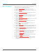
User Guide Introduction Introduction Printer features This printer is a document printer for printing manually inserted documents as well as passbooks (vertical and horizontal fold passbooks). Manual insertion of the documents is supported by an automatic document alignment function. The printer has a high processing speed and compact design. The 24-needle print head guarantees excellent print quality.
Introduction About this manual User Guide This user guide contains a detailed description of the printer, its characteristic features and additional information. ` Chapter 1 Printer at a glance lists all the parts of the printer. ` Chapter 2 Installation contains start-up instructions and points to no- te. ` Chapter 3 Printer drivers and firmware provides instructions for in- stalling the printer driver. ` Chapter 4 Control panel explains how to control printer operations.
User Guide 1 Printer at a glance Printer at a glance View from the front Cover Power switch (On/Off) Control panel Paper tray View with cover opened Ribbon cassette Release lever Print head 3
Printer at a glance User Guide View from the rear Power inlet 1st Serial interface Parallel interface 4 USB interface 2nd Serial interface (special version)
User Guide 2 Installation Installation Unpacking the printer Place your packaged printer on a solid base. Make sure that the “Up” symbols is pointing up. Open the packaging, lift the printer out of the cardboard box and remove the remaining packaging material. Check the printer for any visible transport damage and missing items.
Installation User Guide Placing your printer Place the printer on a solid, flat, surface, ensuring that the printer is positioned in such a way that it can not topple, and that there is easy access to the control panel and paper input tray. Also ensure there is sufficient space for the printed output. min. 1 cm min. 1 cm min. 2 cm min.
User Guide Installation When selecting the printer location, observe the following additional instructions: STOP Never place the printer in the vicinity of inflammable gas or explosive substances. ` Protect the printer from shock, impact and vibration. ` Be sure to connect the printer to a socket with the correct mains voltage. ` Do not expose the printer to direct sunlight. If you cannot avoid pla- cing the printer near a window, protect it from the sunlight with a curtain.
Installation User Guide Checking the printer voltage Make sure that the device has been set to the correct voltage (e.g. 230 V in Europe, 120 V in the USA). To do this, check the type plate at the back of the printer. Contact your dealer if the setting is incorrect. STOP Never switch on the printer if the voltage setting is incorrect, since this may result in severe damage to the printer. Type plate Connecting the printer Connect the power cable to the power inlet of the printer.
User Guide Installation Make sure that the printer and the computer are switched off and connect the data cable between the printer and the computer. This example shows a 36-pin centronics parallel cable.
Installation User Guide Switching on the printer Before switching the printer on, make sure that it is connected correctly and that you have followed all the safety and installation instructions (see section Placing your printer, page 6). Press the power switch which is located at the front bottom right of the printer to switch on the printer. The printer initializes.
User Guide 3 Printer drivers and firmware Printer drivers and firmware Printer drivers You must install a printer driver so that the printer can process the data from your application programs. An original driver offers the best conditions for optimal printing results. All available Windows printer drivers can be found on the CD-ROM en-closed with the printer, and also from our Internet site, from which you can download updated versions as required.
Printer drivers and firmware User Guide in one of two possible ways: ` Manual installation of printer driver: in this case, continue with Step 7. ` Automatic installation of printer driver via Plug & Play function: in this case, continue with Step 12 once the printer installation wizard has determined the printer, port and printer name. Then click on Next. 7. Select the port to which your printer is connected, then click on Next. 8. Click on Data Carrier, then click on Browse. 9.
User Guide Printer drivers and firmware Installing a printer driver in Windows 7 The online CD-ROM contains printer drivers for the most common Windows applications. To install the printer driver, proceed as follows. 1. Insert the supplied online CD-ROM in the CD-ROM drive. 2. Click on the Start button in the Windows taskbar. 3. Click on Devices and Printers to open the printer folder. 4. Click on Add a Printer in the menu bar. 5.
Printer drivers and firmware User Guide the relevant option. Then click on Next. 13. Specify whether you wish to print out a test page (recommended) by selecting the relevant option and click on Finish. The printer driver will now be installed. Installing a printer driver in Windows Vista The online CD-ROM contains printer drivers for the most common Windows applications. To install the printer driver, proceed as follows. 1. Insert the supplied online CD-ROM in the CD-ROM drive. 2.
User Guide Printer drivers and firmware 13. If you are using the printer as a network printer, you have the option of sharing it with other network users. In this case you must enter an access name which will be displayed to the other network users. Then click on Next. 14. If required, edit the name of the default printer and specify whether you wish to use the printer as a default printer by clicking on the relevant option. Then click on Next. 15.
Printer drivers and firmware Form settings (Windows 2000/2003/XP/ Vista/Windows 7/2008) User Guide In contrast to Windows versions 95/98, in which forms are defined in the printer driver itself, Windows versions 2000/2003/XP/Vista/Windows 7/2008 have a central facility for managing form properties and assign one paper feed only. If you want to set up a form not included in the Windows default settings, proceed as follows. You will need Administrator rights to define new forms. 1.
User Guide Loading firmware Printer drivers and firmware The most current version of the firmware can be downloaded from our Internet site. There you will find also additional informations regarding the firmware and printer upgrades. Make sure that the download consists of the following files: ` Standard Model PB Flash VX.XX.exe: the memory writer (flash) ` BL_XXXX.IPL: Bootblock of the printer ` FWXXXX.mfw: Main firmware of the printer ` PBCGXXXX.
Printer drivers and firmware User Guide Parallel interface Make sure that the parallel interface is selected in the printers menu for USER1, that in the PCs BIOS the parallel port is set to ECP and that the parallel cable meets the IEEE1284 standard. USB interface (Windows2000/ XP) Make sure that the USB interface is selected in the printers menu for USER1, that a printer driver has been installed and the printer is defined as default printer.
User Guide 4 Control panel Control panel The control panel allows the user to set some functions in the printer and set up the basic printer parameters on installation. The control panel is located on the front right side of your printer and consists of a two-line LC display with 2 x 16 digits, three keys for controlling the printer functions and four LED indicators displaying the status of the printer. The functions of the keys depend on the printer’s current mode (status). There are three basic modes.
Control panel User Guide Display, indicators and keys 1 ONLINE NO PAPER 2 3 4 5 PAPER SETUP USER1 STOP USER2 /EJECT 8 7 6 LCD display: Displays the internal printer status, operating instructions and error messages. 2 Paper LED: Indicates whether paper is loaded; on = paper is inserted, off = no paper inserted; blinking = indicates that data has been sent to the printer.
User Guide Control panel Status indicators Status indicator variations This section defines the status of the control panel. The LED lights will be on, off or blinking coupled with messages from the LCD. In this way the printer reports its current status.
Control panel User Guide Ready indicator (STOP LED) PAPER Ready indicator (STOP LED) not lit: ` The printer is in the stop status (Offline) and will not receive data from the system. USER1 STOP USER2 /EJECT SETUP PAPER Ready indicator (STOP LED) lit: ` The printer is switched on in the online status. It is ready to receive data from the system. USER1 STOP USER2 /EJECT SETUP PAPER USER1 STOP USER2 /EJECT SETUP 22 Ready (STOP LED) and Paper indicators (PAPER LED) blink: ` The printer is not ready.
User Guide Control panel Paper indicator (PAPER LED) PAPER Paper indicator (PAPER LED) does not light: ` No paper is inserted in the printer. USER1 STOP USER2 /EJECT SETUP PAPER Paper indicator (PAPER LED) lights: ` Paper is inserted in the printer.
Control panel USER1 and USER2 indicators User Guide The USER1 and USER2 LEDs are normally under the control of the application. They are available to indicate to the user that the appropriate interface is active. Normally in Olivetti, IBM or Epson (Auto)emulations, with dual host connections they will indicate that a job is available for the interface associated with the USER.
User Guide Control panel Key functions during operation STOP/EJECT key ONLINE NO PAPER PAPER SETUP STOP NO PAPER PAPER SETUP ONLINE PAPER USER1 STOP USER2 /EJECT PAPER SETUP XXXXX XXXXX USER1 STOP USER2 /EJECT PAPER SETUP DATA NO PAPER USER1 STOP USER2 /EJECT USER1 STOP USER2 /EJECT PAPER SETUP USER1 STOP USER2 /EJECT With the Ready indicator lit, the printer is ready to recieve data from the host. You can switch the printer from online to offline by pressing the STOP/EJECT key.
Control panel User Guide USER1 and USER2 key ONLINE PAPER PAPER SETUP USER1 STOP USER2 /EJECT The USER1 and USER2 keys are by default inactive. They must be activated via an application. The functionality of the keys then depend on the selected emulation and the sequences sent to the printer. For more information on emulations and sequences please refer to the programmer’s application manual.
User Guide Control panel Key functions when powering on STOP/EJECT key PAPER SETUP USER1 STOP USER2 /EJECT Powering on the printer whilst holding the STOP/EJECT key will activate “Hex Dump” mode. Keep the STOP pressed until the message Hex Dump NO PAPER appears on the LCD display. Refer to the section Hex Dump, page 65, for a description of how to activate/deactivate and perform the test printout.
Control panel User Guide USER1 key PAPER SETUP 28 USER1 STOP USER2 /EJECT Powering on the printer whilst holding the USER1 key will allow you to enter menu mode. Keep the USER key pressed until the message MENU USER appears on the LCD display. Refer to the section Menu parameters, page 59, for further details on the menu mode.
User Guide Control panel Key functions in menu mode In menu mode the control panel keys have the following functions USER1 key PAPER MENU COMMON SETUP USER1 STOP USER2 /EJECT The USER1 key is used to go to the next parameter group or next parameter on the same menu level (symbolized by an arrow pointing upwards). It is also used to change parameter settings. For further details refer to the section Menu handling, page 49.
User Guide 5 Print media Print media Inserting a document Before inserting a document make sure that the printer is switched on and the the message ONLINE NO PAPER is displayed in the LCD (see Switching on the printer, page 10). Insert the document in such a way that the right paper edge is positioned inside the area between the left side of the symbol and the right edge of the document support, so that the document alignment can grasp it securely.
Print media Inserting a passbook User Guide Before processing a new vertical-fold or horizontal-fold passbook, you should eliminate the stiffness of the fold by proceeding as follows. Open the passbook on the page that you want to print. Bend the fold backwards extremely hard. Stroke along the fold of the passbook with both thumbs and index fingers and slightly bend the passbook outwards. To print a new passbook, repeat this procedure several times.
User Guide Print media The bulge of the opened passbook should be as flat as possible to ensure trouble-free transportation into the paper. Place the passbook on the right-hand side of the document support with the page to be printed facing up. The passbook must be entered into the opening of the chute. Once in the chute the printer mechanism will take the book. At this point you may release the book, as the printer will align it against it's right stop position and load it into the printer.
Print media User Guide After the passbook is printed, it should be automatically ejected from the printer and released for removal. If the passbook has not successfully ejected from the printer, press the STOP key to to take the printer to STOP (Offline) mode: press the STOP key again to eject the passbook. ONLINE NO PAPER The message ONLINE NO PAPER appears on the LCD again.
User Guide 6 Changing the ribbon cassette Changing the ribbon cassette Make sure that the printer is switched off before replacing the ribbon cassette. STOP The print head may be hot if the printer has been printing for a long time. Wait until it cools to a temperature safe for handling. Removing the ribbon cassette Open the top cover by grasping it at the right and left-hand sides and swing upward until it clicks into position. Press the green release lever in the printing mechanism.
Changing the ribbon cassette User Guide Remove the colored ribbon guide from the print head by pulling it downwards. Raise the front end of the ribbon cassette on both sides. Take the ribbon cassette out of the printer. Ensure proper disposal of used ribbon cassettes in accordance with the applicable national laws and regulations.
User Guide Inserting the ribbon cassette Changing the ribbon cassette Take the new ribbon cassette from the packaging and remove the transportation lock which fixes the ribbon guide to the cassette. First insert the new ribbon cassette by hooking it into the rear slots of its mountings. Push the front of the cassette into its mounting so that it clicks into position. Please do not press the center of the ribbon cassette as this will deform the ribbon cassette and will cause operation problems.
Changing the ribbon cassette User Guide Pull the ribbon guide under the print head. Tighten the ribbon by turning the tension gear in the direction of the arrow (see image below). Press the ribbon guide onto the print head from underneath until you hear it click into place. Check if the ribbon is transported correctly by turning the tension gear in the direction of the arrow.
User Guide Changing the ribbon cassette Close the main frame by pressing the colored section in the middle of the frame as shown and ensure both left and right hand sides of the frames are fully latched. Close the cover. The printer is now ready to operate and to be switched on again. We recommend to check the printer's operation after replacing the ribbon cassette by performing a printout of the parameter settings (see section Printing out the status page, page 55).
User Guide 7 Replacing the print head Replacing the print head As the print head has a very long life, under normal circumstances it rarely needs replacing. STOP Always take care not to print over the edge or on a fold or perforation, as this can damage the needles of the print head. Damage of the needles will lead to a bad print image. Should the print head be defective, you can replace it. Proceed as described below. Be sure to switch the printer off before you replace the print head.
Replacing the print head User Guide Press the green release lever for the printing mechanism. This swings the printing mechanism backwards. STOP If the printer has been printing for a long time, the print head can be hot. Wait until it has cooled to a temperature suitable for handling. Move the print head to center of the carriage to allow enough room to remove the ribbon guide from the print head. Remove the colored ribbon guide from the print head by pulling it downwards.
User Guide Replacing the print head Remove the two outside located screws A from the print head. Disconnect the two flexible cables B from the print head. B A Now remove the print head from its mounting by easing it forward. Ensure proper disposal of the print head in accordance with the applicable national laws and regulations.
Replacing the print head User Guide Inserting new print head Ease the new print head down into the mounting. Set the print head onto the center of area A. A Fasten the two screws A. Connect the flexible cables B to each connector. Make sure to push them fully into the connectors; do not kink the cables.
User Guide Replacing the print head Pull the ribbon guide under the print head. Tighten the ribbon by turning the tension gear in the direction of the arrow (see image below). Press the ribbon guide onto the print head from underneath until you hear it click into place. Ensure that the ribbon material is moving correctly by turning the tension gear in the direction of the arrow.
Replacing the print head User Guide Close the main frame by pressing the colored section in the middle of the frame as shown and ensure both left and right hand sides of the frames are fully latched. Close the cover. The printer is now ready for operation and can be switched on again. We recommend to check the printer's operation after replacing the print head by performing a printout of the parameter settings (see section Printing out the status page, page 55).
User Guide 8 Menu Menu Programming using the control panel As well as being able to control your printer via your applications software you use, you can also program the printer directly. There are two programming options you can use: ` Programming via the control panel. ` Programming via the interface using Escape sequences or control codes. Settings made by escape sequences have priority over settings made in menu mode; therefore they will override these.
Menu User Guide Calling up the menu You can access the menu in the following way: Ensure the printer is powered off. Power on the printer whilst holding the USER1 key. PAPER SETUP USER1 STOP USER2 /EJECT The printer initialises and the LCD displays the message: PAPER MENU COMMON SETUP Menu configurations (USER1/USER2) USER1 STOP USER2 /EJECT Every printer is shipped with factory default settings. Basic settings such as emulation, character pitch, form length etc.
User Guide Menu Menu handling Key functions You can navigate in the current menu using the three keys of the control panel. USER1 key In menu mode the USER1 key has the following functions: MENU COMMON Press the USER1 key to return to the previous parameter group or parameter on the same menu level. PAPER SETUP USER1 STOP USER2 /EJECT The USER1 key is also used for changing parameter settings (see also STOP/EJECT key, page 50).
Menu User Guide Return to Prev. Layer SETUP USER1 STOP USER2 /EJECT PAPER MENU COMMON SETUP * 50 USER1 STOP USER2 /EJECT PAPER SETUP If pressed in a main menu level the next menu level is selected (e.g. MENU USER > Default Set USER1). USER1 STOP USER2 /EJECT PAPER SETUP Default Set Menu2 Accepted By pressing the STOP/EJECT key you will return to the previous menu layer (see also STOP/EJECT key, page 50).
User Guide Menu Setting parameters (principle) Before you begin setting the parameters, you should check which parameters your system requires. Furthermore it is recommended to print out the status page which contains the actual valid parameter values (see Printing out the status page, page 55). The initial values, which are activated after switching on or after error correction, are determined using the adjustable printer parameters.
Menu User Guide Press the USER2 key to select a next parameter value or press the USER1 key to select a previous parameter value. PAPER SETUP USER1 STOP USER2 /EJECT Press STOP/EJECT key to save a parameter value. In the second line of the LCD display the message Accepted appears. Press STOP/ EJECT key again to confirm the setting.
User Guide Menu This section describes how to make settings in the menu, using the selection of the national language as an example. Selecting the LC display language This example shows how to change from the English language to the German language. The same procedure applies to the other languages (French, Italian, Spanish and Turkish). Make sure that the printer is in menu mode (see section Calling up the menu, page 48).
Menu User Guide Sprache Deutsch akzept. PAPER USER1 STOP USER2 /EJECT SETUP Zuruck zur vorh. Ebene PAPER SETUP Zuruck zur vorh. Ebene PAPER To navigate to the previous menu level, press the USER1 key repeatedly until the message Zurück zur vorh. Ebene (Return to Prev. Layer) appears in the LCD display. Press the STOP/EJECT key. Press the USER1 key.
User Guide Menu Printing out the status page The printer has a function that allows you to printout the current parameter settings. There are two ways to print out the parameter settings. ` Power on + USER2 key ` Selection of “Test Print Status Page” in menu mode Power on + USER2 key Power the printer off. Press and hold the USER2 key while switching on the printer. PAPER SETUP USER1 STOP USER2 /EJECT Print StatusPage Load Paper PAPER The LCD displays Print StatusPage Load Paper.
Menu User Guide Print out status page in menu mode Power the printer off. Press and hold the USER1 key while switching on the printer. PAPER SETUP USER1 STOP USER2 /EJECT PAPER MENU COMMON SETUP MENU Print StatusPage Print StatusPage Load Paper 56 Insert the paper in the printer. The LCD displays Print StatusPage Printing... and the status page is printed. USER1 STOP USER2 /EJECT PAPER SETUP Press the STOP/EJECT key. USER1 STOP USER2 /EJECT PAPER SETUP Print StatusPage Printing...
User Guide Menu Print StatusPage Completed When the test printout is aborted or completed, LCD will display Print StatusPage Completed. PAPER SETUP USER1 STOP USER2 /EJECT Press the STOP/EJECT key to return to menu mode. If you want to terminate Setup Mode after the printout of the status page, hold the STOP/EJECT key pressed for three seconds after Print StatusPage Completed is displayed. Setup mode will be ended and a reset will be performed.
Menu Status page (example) 58 User Guide
User Guide Menu Menu parameters The following section introduces and explains all the possible menu settings. The default setting is marked by an asterisk (*) Parameter group Parameter Possible settings Description MENU COMMON Default Set Off All Menu 1 Menu 2 Copy Menu Menu1 to Menu2 * Menu2 to Menu1 Copies the settings of Menu 1 to Menu 2 and vice versa. Change Menu Menu1 Menu2 * Defines if the parameter settings of Menu 1 or of Menu 2 are changed.
Menu Parameter group MENU PAPER FORMAT User Guide Parameter Possible settings Font Draft Draft Banking Courier Roman Sans Serif Gothic OCR-A OCR-B Code Page 437*, 850, 860, 863, 865, 851, 852, 853, 855, 857, 866, 869, USSR Gost, 864, 437G, 920 (8859-9), 858, 923 (8859-15), ISO 8859-2 East Europe, ISO 8859-5 Cyrillic, ISO 8859-7 Greece, ISO 8859-8 Hebrew, 1250 Windows Latin2, 1251 Windows Cyrillic, 1252 Windows Latin1, 1253 Windows Greek, 1254 Windows Latin5, 1255 Windows Hebrew, 1256 Windows Arabic
User Guide Parameter group Menu Parameter Possible settings Description Top of form pos. 0/60 Sets the position of the first printing line. The factory setting for the first printing position is 10/60" (4,23 mm). This is equivalent to the second line from the top. I 10/60 I * 60/60 Bottom edge1) 0/60 30/60 * Sets the distance between last printing line and bottom edge.
Menu Parameter group User Guide Parameter Possible settings Description Paper ejection drop hold * Selects the paper position after paper ejection. Message display Off On * Selects displaying messages on or off in Olivetti, EPSON and IBM 4722 emulation. NOTE: These messages will not be displayed if IBM Proprinter XL is selected as Emulation Type.
User Guide Parameter group Menu Parameter Possible settings Description Protocol Ready/Busy Xon/Xoff * Selects the type of protocol, i.e. a certain set of rules and procedures for ensuring error-free data exchanges between computer and printer. Details of the available protocols can be found in the section Serial attachment characteristics, page 131. CTS Valid Invalid * Sets the signal CTS (Clear To Send) on or off.
Menu User Guide Parameter group Parameter Possible settings MENU Epson Emulation type US-ASCII France Germany Great Britain Denmark 1 Sweden Italy Spain 1 Japan Norway Denmark 2 Spain 2 Latin America Character Table Italic Graphic1 Graphic2 MENU IBM Description * * Selects the national character set in Epson emulation. The character sets are not necessarily available for all fonts; see also section Available code pages and fonts, page 106. Only available for Epson emulation.
User Guide Menu Test function With the interface mode (Hex-Dump/H-Dump) you can diagnose data transmission from the computer to the printer. In this special mode, the data from the computer is printed out in two columns. The text in the left column is printed in hexadecimal format and in the right column in ASCII format. This can be used to diagnose print problems. Hex Dump Some applications require status response from the printer. In such case Hex Dump is ineffective for diagnosing problems.
Menu Hex Dump Load Paper User Guide SETUP Exiting the test mode Test printout Hex Dump (Example) USER1 STOP USER2 /EJECT You can only exit the test mode by switching off the printer. Address 0000 0010 0020 0030 0040 0050 66 If the printer receives data when there is no paper in the printer, the message will be changed to Hex Dump Load Paper. PAPER Hex data 00 10 20 30 40 50 01 11 21 31 41 51 02 12 22 32 42 52 03 13 23 33 43 53 04 14 24 34 44 54 05.... 0C 15.... 1C 25.... 2C 35.... 3C 45..
User Guide 9 Troubleshooting Troubleshooting Many of the faults and problems which may occur while using the printer are minor problems which you can solve yourself. The following chapter should help you to distinguish between a simple operating error and a major malfunction. This chapter provides information on the rectification of faults without the assistance of specially trained personnel. Follow the advice and tips in this chapter if your printer is not working correctly.
Troubleshooting User Guide General print problems Problem Corrective action The display remains dark Switch off the printer and proceed as follows: The printer is switched on, but nothing happens (nothing is displayed, no noise). 1. Check that the power plug is correctly connected to the socket on the printer. 2. Check that the power plug is seated properly in the wall socket. 3. Switch on the printer again.
User Guide Troubleshooting Problem Corrective action Problems with paper feed 1. Check that the correct media type is selected in the menu, if necessary select the correct media type. See section Media, Paper will not load or feed page 61. 2. Check if the right edge of the document is positioned inside the area between the left side of the symbol and the right edge of the document support. See section Inserting a document, page 31. 3. Make sure that the paper meets the paper specifications.
Troubleshooting User Guide Problems with the print quality Problem Corrective action Print is faulty The inserted document is too thick. Use a document with the correct thickness. Refer to the section Paper specifications, page 87 and the chapter Print media, page 31. Print is too pale The ribbon exhausted or the ribbon cassette is not correctly fitted. Refer to the chapter Changing the ribbon cassette, page 35. Smudged print The ribbon is damaged (e.g. frayed).
User Guide Error messages and warnings Troubleshooting Malfunctions are differentiated as warnings and errors. For a warning a message only appears on the LCD briefly. As soon as the control logic of the printer detects an error, it aborts the printout and the Ready and the Paper indicators on the control panel starts to blink. An error message is issued on the LCD. The cause of this malfunction and the possible troubleshooting actions are listed in the following table.
Troubleshooting Unrecoverable errors User Guide The following errors are unrecoverable by the user. If displayed in the LCD display, power the printer off and on again. ` CAM Error ` Carrier Error ` RAM Error ` ROM Error ` EPROM Error ` CG Error ` MSR-H Error ` Key Scan Error If the error message appears again after you have repeatedly powered the printer off and on, contact your dealer or customer service.
User Guide Troubleshooting Recoverable errors Message Condition Corrective action Print Head Hot Error The print head is too hot. ` Power the printer off, open the cover and wait a few minutes. Then power the printer on again. Ribbon Cassette Error Either the ribbon cassette is not installed correctly, the ribbon is not functioning correctly or you are using a ribbon cassette of a different manufacturer.
Troubleshooting User Guide Message Condition Corrective action Framing Error (Serial I/F) The Stop bit is not detected by the serial interface. “?” is printed instead of the received data until the error is canceled. ` If STOP/EJECT key is pressed, the error message is canceled and the printer is in offline (STOP) state. The setting of Parity of the Host PC differs from the Parity setting of the serial interface of the printer. “?” is printed instead of the received data until the error is canceled.
User Guide Troubleshooting Warnings Message Condition Corrective action Data in Buffer USER1 or USER2 key is pressed in online state and there is data in the print buffer. ` When the above-mentioned condition occurs, LCD Message is displayed "Warning Data in buffer" for 3 second and it returns to the original state.Therefore, the function of pressed key is not performed. Remove Paper The paper detection sensor detects a paper after paper ejection was performed.
Troubleshooting User Guide Clearing paper jams If a document which was fed into the printer is not automatically ejected or ejected after pressing the STOP/EJECT key on the control panel after its processing, a paper jam has occurred inside the printer and is displayd in the LCD display. The paper jam must be cleared manually. STOP The print head may be hot if the printer has been printing for a long time. Wait until it has cooled down so that you are not in danger of being burnt.
User Guide Troubleshooting Press the two green release levers on both sides of the panel and lift the panel up. Then remove the jammed paper by pulling it in direction of the arrow out of the printer. Close the main frame by pressing the colored section in the middle of the frame as shown by the white arrow and ensure both left and right hand sides of the frames are fully latched. Close the cover. The printer is now ready to operate and to be switched on again.
User Guide 10 Care and maintenance Care and maintenance The printer is designed to operate with minimal maintenance. It is advisable to clean the inside of the printer from time to time with a vacuum cleaner. STOP Cleaning the housing Before cleaning, turn off the printer, wait 5 to 10 seconds and disconnect the power cable. Do not oil or grease the printer, especially the sliderails and shafts.
Care and maintenance User Guide Cleaning the MSR-H magnetic stripe If your printer has an MSR magnetic stripe reader, the MSR read/write head can be cleaned with a special cleaning sheet as follows. Press the USER1 and USER2 key and keep the key pressed while switching on the printer. PAPER SETUP USER1 STOP USER2 /EJECT MSR-H Cleaning Load Paper PAPER SETUP The message MSR-H Cleaning Load paper appears on the LCD display.
User Guide MSR-H Cleaning OK MSR-H Cleaning Error Care and maintenance After finishing the cleaning process the LCD displays the Message MSR-H Cleaning OK. PAPER USER1 STOP USER2 /EJECT SETUP PAPER SETUP USER1 STOP USER2 /EJECT You can repeat the cleaning routine by pressing the STOP/EJECT key. If an error occurs during the cleaning process, the LCD displays the message MSR-H Cleaning Error after the cleaning action has ended.
Care and maintenance User Guide Transport of the printer Preparations for transport STOP If you intend to transport the printer over a short distance only, ensure that it has been switched off correctly. Never remove the mains plug when you can still hear mechanical noise. Make sure that the printer is transported horizontally. Don’t tilt the printer nor put it upside down. Keep the packaging for future transportation.
User Guide A Specifications Specifications Printer specifications Printer system Serial impact matrix printer Printhead with 24 needles Diameter 0.23 mm Print speed Draft (High Speed) CPI 10 12 15 16.6 17.1 20 CPS 400 480 600 400 342 400 Draft (Normal) CPI 10 12 15 16.6 17.1 20 CPS 300 360 400 200 228 266 Letter Quality (High Speed) CPI 10 12 15 16.6 17.1 20 CPS 133 160 200 200 228 266 Letter Quality (Normal) CPI 10 12 15 16.6 17.
Specifications User Guide Fonts Standard CG Draft LQ Optional CGs Draft Draft Banking Courier Roman Sans Serif Script OCR-A1) OCR-B Bold Gothic Prestige Elite Orator 1) If OCR-A font is selected, the code page will automatically select DIN as code page.
User Guide Specifications Apparent power consumption Operation (maximum): US: 89.7 VA; EU: 93.6 VA Standby: US: 8.8 VA; EU: 11.4 VA Noise Sound output level Sound pressure level LWAd: 7.1 dB in operation LpAm: 55 dB in operation Paper feed Friction feed MTBF (Mean Time Between Failures) 10,000 power on hours at 25% DC (duty cycle) Dimensions Height: Width: Depth: Weight Standard = 9.10 kg, MSR-H = 9.
Specifications User Guide Approvals 86 DIN EN 60 950 / VDE 0805, TUV (EN 60950) / Certified CE Mark, UL 60950 3rd Edition / C-UL (CSA C22.
User Guide Paper specifications Specifications Single and multi-copy sheet Paper width 70 to 240 mm Paper length 70 to 500 mm Paper weight Single sheet: Multi sheet: 60 to 160 g/m2 80 to 260 g/m2 Paper thickness Single sheet: Multi sheet: 0.08 to 0.5 mm 0.08 to 0.
Specifications 88 User Guide Paper quality Light pulp paper of medium fine quality, paper bearing the quality mark SM Post and photocopy paper are suitable for use. Unsuitable are: satin-finish or coated papers, imitation art papers, and embossed papers. Since paper as natural material reacts strongly to environmental influences (e.g. humidity, temperature), the place of storage should be selected carefully.
User Guide Interface specifications Specifications Parallel interface bidirectional Type of data transmission 8-bit parallel interface (Centronics compatible) IEEE-1284; Nibble and ECP mode Transmission rate Max. 30 KHz Signal status Low: 0.0 V to +0.4 V High: +2.4 V to +5.0 V Connection cable Material: AWG 28 at least Length: up to 2.0 m Twisted-pair cable with double-shield, acc.
User Guide B Character sets Character sets This chapter shows the character sets and contains a list of all available character sets which can be selected via control panel or by escape sequences. The following example shows you how to find the hexadecimal value for a character from the symbol set tables. hex dec 0 1 2 3 0 1 2 NUL 3 4 SP 0 16 32 48 64 1 17 33 49 65 2 18 34 50 66 3 19 35 51 67 ASCII “B” = hex.
Character sets OCR-A character set 92 User Guide
User Guide Character sets Epson character sets Italic Graphic1 93
Character sets Graphic2 94 User Guide
User Guide Character sets IBM code pages Code page 437 Code page 850 95
Character sets Code page 860 Code page 863 96 User Guide
User Guide Character sets Code page 865 Code page 851 97
Character sets Code page 852 Code page 853 98 User Guide
User Guide Character sets Code page 855 Code page 857 99
Character sets Code page 866 Code page 869 100 User Guide
User Guide Character sets Code page USSR Gost Code page 864 101
Character sets Code page 437G Code page 920 (equivalent to ISO 8859-9) 102 User Guide
User Guide Character sets Code page 858 Code page 923 (equivalent to ISO 8859-15) 103
Character sets ISO code pages ISO 8859-2 ISO 8859-5 104 User Guide
User Guide Character sets ISO 8859-7 ISO 8859-8 105
Character sets User Guide Available code pages and fonts The following list includes all the character sets you can select from the control panel or via ESC sequences and specifies the fonts in which they are available. The printer does not support all code pages in all the fonts. See the Code page table and notes. n The Roman typeface is selected on these code pages. o The OCR-B typeface are available on ASCII character set and a part of character of code page 437, 850, 860, 863, 865 and 858.
User Guide Font Code page Character sets Draft Draft Banking Roman Sans Serif Courier Bold Prestige Script Orator OratorS Gothic OCR-A OCR-B CP 923 (equivalent to ISO 885915) 9 9 9 9 9 9 9 9 9 9 9 p n ISO 8859-1 Latin 1 9 9 9 9 9 9 9 9 9 9 9 p n ISO 8859-2 Latin 2 9 9 9 9 9 9 9 9 9 9 9 p n ISO 8859-5 Cyrillic 9 9 9 9 9 9 n n n n n p n ISO 8859-7 Greek 9 9 9 9 9 9 n n n n n p n ISO 8859-8 Hebrew 9 9 9 n n n n n n
User Guide C Emulations Emulations When a printer understands the control set written for another printer type, it is said to emulate the other printer. Your printer emulates, i.e. “understands” the Olivetti PR2, the Epson and the IBM emulation in its standard version. Escape sequences Escape sequences or control codes tell the printer that the following transmitted code is a printer command and not a printable character.
Emulations What are escape sequences? User Guide An escape sequence consists of an ESCape control character (ESC = decimal 27 or hexadecimal 1B) followed by one or more characters, which represent commands to the printer. Please note that this escape character has nothing to do with the ESC key on your computer keyboard. For example, the control character ESC followed by the character “4” tells your printer to print the subsequent text in italics.
User Guide Emulations List of available control codes The following table shows the available sequences in the various emulations. If you want to know more about control codes, we recommend our Programmer’s Application Manual on this CD-ROM. Detailled information on PR2 control codes can be found in the original PR2 programmer’s manual.
Emulations User Guide Command sequence Function LF Line feed forward FF Form feed (ejection from rear) CR Carriage return BS Back Space ESC 7 Line feed back ESC H nnn Set absolute horizontal position ESC I nnn Set relative vertical position ESC L nnn Set absolute vertical position ESC O Eject document ESC ^ 0 Change emulation ESC [ nnn Select character set BEL Bell DEL Clear print memory ESC # n Assign reference for ESC L nnn ESC | A nnn Define offset in elementary steps ES
User Guide Emulations Command sequence Function ESC r x Synchronous basic machine status ESC sp B Request for Document Status ESC B id m ESC Z Synchronous Document Status ESC sp b Request for FW Release ID ESC b idrel1;idver1; ...
Emulations User Guide PR50 mode Command sequence Function Page Layout ESC Q nnn mmm ESC Z Define document length ESC J nnn Define left margin ESC T nnn Define top of form " TOF" ESC M nnn Define bottom of form "BOF" ESC & nn Elementary vertical spacing Print Pitches ESC < Print pitch 10 cpi ESC = Print pitch 12 cpi ESC > Print pitch 166 cpi ESC ? Proportional spacing Print Attributes 114 ESC R nnn Select graphic font ESC 3 Double width ESC 4 Cancel double width ESC d Double he
User Guide Emulations Command sequence Function BEL Bell DEL Clear print memory ESC # n Assign reference for ESC L nnn ESC | A nnn Define offset in elementary steps ESC | B nnnn Define document width in elementary steps ESC ' n Set up document type ESC / m nnnn Absolute vertical position in elementary steps ESC - Measure document length ESC } - Measure document width ESC S nnnn Measure document length or width : answer Graphics ESC 1 p mmmm nnn 9 pin BIM print ESC 2 Reset BIM mode
Emulations User Guide Command sequence Function ESC t datiGS Data to be recorded on the magnetic stripe ESC \ Record and verify magnetic stripe ESC Y E k1 K2 Set horizontal magnetic device ESC Y B k1 K2 Set MICR Magnetic Read External paper handling device control 116 ESC } + Form position control ESC } L t nnn Passbook positioning ESC } M nnn Negative bottom of form ESC } W Wait for end of print ESC } 0 P Reset form parking ESC s nnnn Measure form position : answer
User Guide Emulations PR2845 mode Command sequence Function Page Layout ESC Q nnn mmm ESC Z Define document length ESC J nnn Define left margin ESC T nnn Define top of form " TOF" ESC M nnn Define bottom of form "BOF" ESC & nn Elementary vertical spacing Print Pitches ESC < Print pitch 10 cpi ESC = Print pitch 12 cpi ESC > Print pitch 166 cpi ESC ? Proportional spacing Print Attributes ESC R nnn Select graphic font ESC 3 Double width ESC 4 Cancel double width ESC d Double height
Emulations User Guide Command sequence Function BEL Bell DEL Clear print memory ESC # n Assign reference for ESC L nnn ESC | A nnn Define offset in elementary steps ESC | B nnnn Define document width in elementary steps ESC ' n Set up document type ESC / m nnnn Absolute vertical position in elementary steps ESC - Measure document length ESC } - Measure document width ESC S nnnn Measure document length or width : answer Graphics ESC 1 p mmmm nnn 9 pin BIM print ESC 2 Reset BIM mode
User Guide Emulations Command sequence Function ESC t datiGS Data to be recorded on the magnetic stripe ESC \ Record and verify magnetic stripe ESC } r MICR magnetic read ESC Y E k1 K2 Set horizontal magnetic device ESC Y B k1 K2 Set MICR Magnetic Read External paper handling device control ESC } + Form position control ESC } L t nnn Passbook positioning ESC } M nnn Negative bottom of form ESC } W Wait for end of print ESC } 0 P Reset form parking ESC s nnnn Measure form position :
Emulations User Guide IBM mode Command sequence Functions Horizontal position control BS 08H Backspace HT 09H Horizontal tab CR 0DH Carriage return ESC BS 1BH 08H Backspace ESC HT 1BH 09H Horizontal tab ESC CR 1BH 0DH Carriage return ESC D 1BH 44H Set horizontal tabs ESC X 1BH 58H Set horizontal margins ESC d 1BH 64H Relative mode inline forward Vertical position control 120 LF 0AH Line feed VT 0BH Vertical tab FF 0CH Form feed ESC LF 1BH 0AH Line feed ESC VT 1B
User Guide Emulations Command sequence Functions DC4 14H Cancel double-wide printing by line ESC SO 1BH 0EH Double-wide printing by line ESC SI 1BH 0FH Condensed printing ESC DC2 1BH 12H Select 10 cpi ESC DC4 1BH 14H Cancel double-wide printing by line ESC - 1BH 2DH Continuous underscore ESC : 1BH 3AH Select 12 cpi ESC E 1BH 45H Select emphasized mode ESC F 1BH 46H Cancel emphasized mode ESC G 1BH 47H Select double strike mode ESC H 1BH 48H Cancel double strike mode ESC
Emulations User Guide Command sequence Functions BEL 07H Beeper DC1 11H Select printer DC3 13H Deselect printer CAN 18H Cancel Data ESC BEL 1BH 07H Beeper ESC DC1 1BH 11H Select printer ESC DC3 1BH 13H Deselect printer ESC CAN 1BH 18H Cancel data ESC Q 1BH 51H Deselect printer ESC R 1BH 52H Set all tabs to power on settings ESC U 1BH 55H Set print direction ESC [ K 1BH 5BH 4BH Set initial condition ESC j 1BH 6AH Stop printing ESC [ c 19 1BH 5BH 63H 13H Programming
User Guide Emulations Epson mode Command sequence Function Horizontal position control BS 08H Backspace HT 09H Horizontal Tab CR 0DH Carriage Return ESC $ 1BH 24H Set Absolute Print Position ESC D 1BH 44H Select Horizontal Tabs ESC Q 1BH 51H Set Right Margin ESC \ 1BH 5CH Set Relative Print Position ESC a 1BH 61H Select Justification ESC l 1BH 6CH Set Left Margin Vertical position control LF 0AH Line Feed VT 0BH Vertical Tab FF 0CH Form Feed ESC + 1BH 2BH Select n/3
Emulations User Guide Command sequence Function ESC SI 1BH 0FH Select Condensed Mode ESC ! 1BH 21H Master Select ESC ( - 1BH 28H 2DH Select Score ESC - 1BH 2DH Auto Underscore ESC 4 1BH 34H Select Italic Mode ESC 5 1BH 35H Cancel Italic Mode ESC E 1BH 45H Select Emphasized Mode ESC F 1BH 46H Cancel Emphasized Mode ESC G 1BH 47H Select Double-strike Mode ESC H 1BH 48H Cancel Double-strike Mode ESC M 1BH 4DH Select 12 cpi ESC P 1BH 50H Select 10 cpi ESC S 1BH 53H Sele
User Guide Emulations Command sequence Function Others BEL 07H Beeper DC1 11H Select Printer DC3 13H Deselect Printer CAN 18H Cancel Line DEL 7FH Delete Character ESC EM 1BH 19H Set Auto Sheet Feeder Mode ESC SP 1BH 20H Set Inter Character Space ESC # 1BH 23H Cancel MSB Control ESC < 1BH 3CH Select Unidirectional Mode 1 Line ESC = 1BH 3DH Set MSB to 0 ESC > 1BH 3EH Set MSB to 1 ESC @ 1BH 40H Initialize Printer ESC U 1BH 55H Turn Unidirectional Mode On/Off ESC [ c 1
Emulations User Guide Command sequence Function ESC [ n , t 1BH 5BH n 2CH 74H Increasing the copying power ESC [ n ! z 1BH 5BH n 21H 7AH Global printer status ESC [ " z 1BH 5BH 22H 7AH Requesting special printer messages ESC [ n ; m " z 1BH 5BH n m 22H 7AH Special printer messages ESC [ n # z 1BH 5BH n 23H 7AH Requesting printing unit parameters ESC [ n1 ; ... ; n9 # z 1BH 5BH n1 ..
User Guide D Interfaces Interfaces Your printer offers the possibility of operating either via a parallel, a serial or a USB interface. There is also a printer model with a second serial interface. This chapter informs you about the interfaces and describes the communication between your computer and the printer. Interface settings for User 1 and USER2 Your printer allows you to set and use two independent menu configurations for the selection of the interfaces (USER1/USER2).
Interfaces Parallel interface User Guide The bidirectional parallel interface offers the so called “nibble” and the ECP mode of the IEEE1284 interface standard. This enables installation in accordance with Windows “Plug & Play”. The standard parallel interface is able to transfer data at a speed of max. 30,000 bytes per second. When the receiving buffer is full, the data input is blocked until the data buffer is empty. This guarantees data transmission in blocks of 1 KB.
User Guide Interfaces ECP mode Pin Signal In/Out Pin Parallel 1 HostClk In 19 Signal GND 2 DATA0 Bi-Di 20 Signal GND 3 DATA1 Bi-Di 21 Signal GND 4 DATA2 Bi-Di 22 Signal GND 5 DATA3 Bi-Di 23 Signal GND 6 DATA4 Bi-Di 24 Signal GND 7 DATA5 Bi-Di 25 Signal GND 8 DATA6 Bi-Di 26 Signal GND 9 DATA7 Bi-Di 27 Signal GND 10 PeriphClk Out 28 Signal GND 11 PeriphAck Out 29 Signal GND 12 nAckReverse Out 30 Signal GND 13 Xflag Out 31 nReverseRequest
Interfaces Serial interface RS232C User Guide Your printer’s serial interface supports the RS232C specification. The signals are received and transmitted by a 9 pin male connector. Use a serial interface cable that meets the requirements of your host PC. Type RS232C interface Synchronization Asynchronous Transmission rate 4,800 Baud to 38,400 Baud Signal status OFF (log.1) –3 V to –15 V ON (log.
User Guide Interfaces Serial attachment characteristics Data rates The interface supports the following data rates. ` 4800 bps ` 9600 bps ` 19200 bps ` 38400 bps Supported protocols This interface will also support the following: ` 7 or 8 Data Bits ` Even, Odd, None Parity ` 1 or 2 Stop Bit(s) ` Ready/Busy or XON/XOFF handshaking Data Transfer A data frame consists of a start bit, seven or eight data bits, 0 or 1 parity bit(s) and 1 or 2 stop bit(s).
Interfaces Handshake User Guide Handshaking in the serial environment is most commonly handled by software and/or hardware. The manipulation of the hardware handshaking is handled by the following 4 lines: ` RTS (Request to Send) ` CTS (Clear to Send) ` DSR (Data Set Ready) ` DTR (Data Terminal Ready) Ready/Busy (Hardware Handshake) When Ready/Busy protocol is selected, DTR will be used to pace the data flow from PC.
User Guide Interfaces Configuring the serial interface of the PC DOS mode/Command line To use the serial interface of your PC, you must add the following mode commands to the AUTOEXEC.BAT file: mode com1:9600,n,8,1,p mode lpt1:= com1: With the first MODE command, you configure the serial interface Com1 of your PC to the printer’s factory defaults. The second MODE command redirects the parallel standard output port LPT1 of your PC to Com1.
Interfaces USB interface User Guide The USB (Universal Serial Bus) interface has the following features: ` Full compliance with the Universal Serial Bus Specification Revision 2.0 for Full Speed Mode. ` USB Function Controller with two FIFO-based Endpoints: One bidirectional Control Endpoint 0 (8 bytes) One receive Endpoint 1 (1*64 bytes) ` The signaling bit rate is 12 MB/s (Full speed).
User Guide E Consumables and accessories Consumables and accessories Consumables Only use ribbon cassettes from the manufacturer as products from other manufacturers may damage the print head or the ribbon drive. Consumables Ribbon in recyclable cassettes, color: black Accessories Order no. 043393 Only use print heads that are approved to prevent damage to your printer. Accessories Order no.
“All rights reserved. Translations, reprinting or copying by any means of this manual complete or in part or in any different form requires our explicit approval. We reserve the right to make changes to this manual without notice. All care has been taken to ensure accuracy of information contained in this manual. However, we cannot accept responsibility for any errors or damages resulting from errors or inaccuracies of information herein.
TALLY REPRESENTATIVES GERMANY UNITED KINGDOM DASCOM Europe GmbH Heuweg 3 D-89079 Ulm Deutschland Tel.: +49 (0) 731 2075 0 Fax: +49 (0) 731 2075 100 www.dascom.com DASCOM GB Ltd ViewPoint, Basing View, Basingstoke, Hampshire RG21 4RG, England Phone: +44 (0) 1256 481481 Fax: +44 (0) 1256 481400 www.dascom.com SINGAPORE DASCOM AP Pte Ltd 63 Hillview Avenue #08-22, Lam Soon Industrial Building Singapore 669569 Phone: +65 6760 8833 Fax: +65 6760 1066 www.dascom.