TallyCom™ III 2440/2540 Print Server Quick Installation Guide D10586-01 English DASCOM Europe GmbH Heuweg 3 D-89079 Ulm Germany www.dascom.com E-mail: support.de@dascom.com or support.gb@dascom.
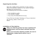
Unpacking the interface Open the cardboard box and take out the content. Check the interface module for any visible transport damage and missing items. The following items should be included: • This installation guide • The interface module • The online CD-ROM (Ethernet only) If you find any transport damage or if any accessories are missing, please contact your dealer. Installation of the interface Make sure that the printer has been switched off and the power cord has been removed from the printer.
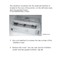
The interface connection for the optional interface is located at the rear of the printer, on the left side (seen from the printers front). It is protected by a cover. 1 Use a screwdriver to remove the two screws of the interface cover. 2 Remove the cover. You can now see the interface socket and two guides (bottom, top) A.
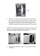
3 Take the interface module and make sure that the two screw openings are pointing to the right. Slide the interface module into the guides and push it carefully into the printer until the connector of the interface module is properly seated into the socket. Fasten the interface module with the two screws to the printer. The left example shows the RS232C interface, the right example the Ethernet interface. 4 Connect the interface cable to the printer and the computer.
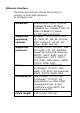
Ethernet interface The Ethernet interface affords the printer to connect to local area networks. Its attributes are: Hardware Supported operating systems Supported protocols Set-up Management Cable length LAN/Ethernet: RJ45, Ethernet 100BaseTX with 100 Mbps (IEEE802.3u), 10Base-T with 10 Mbps (IEEE802.
For more information on Ethernet interface specifications, refer to the User Guide on the Online CD-ROM delivered with the Ethernet interface.
IP address The IP address, subnet mask and gateway address can be set in the menu of the printer via the control panel. Printer LEDs The LEDs of the Ethernet signal different modes. • Yellow only: The LED will blink once every second until an IP address is assigned. The LED blinks faster or lights constantly, if there is an error. If this is the case, check cables and restart the TallyCom III™. • Green only: TallyCom III™ is receiving data from the network. • Yellow and Green: Lights up shortly at power on.
NOTE: This equipment has been tested and found to comply with the limits for a Class B digital device, pursuant to part 15 of the FCC Rules. These limits are designed to provide reasonable protection against harmful interference in a residential installation. This equipment generates, uses and can radiate radio frequency energy and, if not installed and used in accordance with the instructions, may cause harmful interference to radio Communications.