Host Print Set-up Guide D10588-01 October 2009 DASCOM Europe GmbH Heuweg 3 D-89079 Ulm Germany www.dascom.com E-mail: support.de@dascom.com or support.gb@dascom.
Table of contents 1 PSF/MVS AFP Printing Using TCP/IP .................................................. 3 1.1 PSF/MVS direct attachment ..............................................................3 1.2 PSF/MVS start-up procedure .............................................................3 2 z/OS SCS Printing Using TN3270e ...................................................... 5 2.1 TN3270E Setup using z/OS Communication Server ..............................5 2.1.
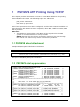
1 PSF/MVS AFP Printing Using TCP/IP This chapter provides information on how to create MVS definitions for printing from PSF/MVS via TCP/IP. The following topics are addressed: JES printer statements PSF Start-up procedure Once these parameters have been configured, and the basic TCP/IP installation of the PrintServer with IPDS has been completed, direct AFP / IPDS from PSF / MVS will be possible.
//*------------------------------------------------------------------//FDEF01 DD DSN=SYS2.FDEFLIB,DISP=SHR /* SYSTEM FORMDEFS */ // DD DSN=SYS1.FDEFLIB,DISP=SHR /* SYSTEM FORMDEFS */ //******************************************************************** //* STANDARD PRINTDEV */ //******************************************************************** //PRT420 CNTL //PRT420 PRINTDEV FONTDD=*.FONT01, /* FONT LIBRARY DD */ // OVLYDD=*.OLAY01, /* OVERLAY LIBRARY DD */ // PSEGDD=*.
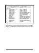
2 z/OS SCS Printing Using TN3270e This chapter provides examples of how to set up SCS printing using TN3270e. 2.1 TN3270E Setup using z/OS Communication Server The IBM z/OS is capable of supporting TN3270e sessions communicating directly. The following describes the required mainframe definitions for a LinkCom or DocOut. It is assumed that the TN3270e service is already active on the mainframe. 2.1.
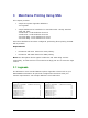
3 Mainframe Printing Using SNA This chapter provides: • sample LU1 printer logmode definitions: 3.1 Logmode • sample definitions for installation in association with a locally attached 3174 and 3745: 3.2 Ethernet - PS PU definition for 3174 3.3 Ethernet - PS PU definition for 3745 3.4 Token Ring - PS PU definition for 3174 3.5 Token Ring - PS PU definition for 3745 Once these definitions have been configured, performing direct printing via SNA will be possible.
3.2 Ethernet - PS PU definition for 3174 Sample definition for installation in association with a locally attached 3174.
PrintServer Definition file extract &&??##N1,0# ; Start of file - Don't remove this ! ;-----------------------------------------------------------------------; Configuration for the Ethernet PrintServer ; (This is an example. Please modify the parameters to match ; your configuration).
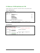
3.3 Ethernet - PS PU definition for 3745 Sample definition for installation in association with a locally attached 3745.
PSF JCL //PRTN //PRTN // // // // // // // // // // // CNTL PRINTDEV FONTDD=*.FONT300, OVLYDD=*.OLAY01, PSEGDD=*.PSEG01, PDEFDD=*.PDEF01, FDEFDD=*.FDEF01, JOBHDR=*.JOBHDR, JOBTRLR=*.JOBTLR, DSHDR=*.DSHDR, MESSAGE=*.
3174 Definition ****************************************************************************** LOCAL TOKEN RING DEFINITION 3174 * CHANNEL ADDRESS 1C1-1C8 * 3174 /11L Microcode EC=A78831 ML=90095 * Prompt 900 - 400031740001 * Token-Ring Gateway Address * * Prompt 940 * Token-Ring Assignment * C1 - 40005A0001C1 * C2 - 40005A0001C2 * C3 - 40005A0001C3 * Prompt 941 * Token-Ring Address Configuration * SAP F W * C1 - 40005A00001C1 4 3 3 * C2 - 40005A00001C2 4 3 3 * C3 - 40005A00001C3 4 3 3 11
PrintServer Definition file extract &&??##N1,0# ; Start of file - Don't remove this ! ;-----------------------------------------------------------------------; Configuration for the Token Ring PrintServer ; (This is an example. Please modify the parameters to match ; your configuration).
3.5 Token Ring - PS PU definition for 3745 Sample definition for installation in association with a locally attached 3745.
PSF JCL //PRTN CNTL //PRTN PRINTDEV FONTDD=*.FONT300, /*FONT LIBRARY DD */ // OVLYDD=*.OLAY01, /*OVERLAY LIBRARY DD */ // PSEGDD=*.PSEG01, /*SEGMENT LIBRARY DD */ // PDEFDD=*.PDEF01, /*PAGEDEF LIBRARY DD */ // FDEFDD=*.FDEF01, /*FORMDEF LIBRARY DD */ // JOBHDR=*.JOBHDR, /*JOB HEADER SEPARATOR OUTPUT // JOBTRLR=*.JOBTLR, /*JOB TRAILER SEPARATOR OUTPUT // DSHDR=*.DSHDR, /*DATA SET HEADER SEPARATOR // MESSAGE=*.
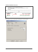
4 Configuration of MS SNA/HIS Server This chapter provides examples of how to set up SCS printing using TN3270e. 4.1 General setup 4.1.1 Adding DLC 802.2 protocol to your Windows Server / Workstation In order to communicate via Token ring or Ethernet over SNA, you must add the DLC protocol to your Windows Server or Workstation running SNA Server.
4.1.2 SNA Server configuration – Create a link You must define the Server LAN card to be used to communicate with the host. - Folder Link Services, make a right click and select Link Service. Select DLC 802.2 Link Service from the list. - In the DLC 802.2 Link Service Properties window, select the LAN card you want to use. 4.1.
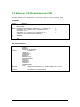
Connections : General Connections : Address Note : Remote Network Address must match the Host MAC Address (TIC) 17
Connections : System Identification Note : local Node ID must match the ID_NUM and ID_BLOCK parameters of the VTAM PU Definition Connections : System Identification Note : MAX BTU Length must match the MAX_DATAD parameter of the VTAM PU Definition 18
4.2 SNA Server configuration – Create a Printer LU Attached to the connection, you must create your printer LU. In order to run with MPI Router, you must define a LUA LU. - Make a right click on your connection and select Application LU (LUA).
4.3 Configuring BlueServer for SNA communication 4.3.1 Setup Connection tab Notes: - The other tabs “IPDS Settings”, “Paper Controls”, are not used in this case. - The SCS Settings tab is only used only for SCS printout.
4.4 Loading the Router Mainframe and Parser 4.4.1 Microsoft SNA/HIS status indication The PSNA201 is SSCP 4.4.2 Blue Server status indication With this configuration, you are now able to print SCS or IPDS jobs from your Mainframe IBM host.
4.5 Configuring DocOut for SNA communication 4.5.
4.5.2 Microsoft SNA/HIS status indication The PSNA201 is SSCP 4.5.3 DocOut status indication With this configuration, you are now able to print SCS or IPDS jobs from your Mainframe IBM host.
5 PSF/AIX IPDS Printing Using TCP/IP This chapter provides details on: Adding a TCP/IP attached printer Set up of the KEEPALIVE TCP/IP feature The basic TCP/IP installation of the PrintServer (IPDS) must be completed before direct AFP / IPDS from PSF/AIX will be possible. 5.1 Adding TCP/IP attached printer The port number is defined in the PSF/AIX SMIT Add a TCP/IP-Attached Printer panel. 1. Enter Printer name PSF/AIX uses the printer name you specify. Enter a name of up to 8 characters. 2.
In the following, you are provided with instructions for using the KEEPALIVE support facility added to the TCP/IP components for AIX 5.3 AIX KEEPALIVE support The no (network options) command can be used by the root user to configure KEEPALIVE frequencies. no -o tcp_keepidle=nnn no -o tcp_keepintvl=nnn when nnn is in half-seconds. The command tcp_keepidle specifies the interval of inactivity causing the TCP to generate a KEEPALIVE transmission for an application that requests them.
6 PSF/400 AFP Printing Using TCP/IP This chapter provides configuration guidelines for AS/400 IPDS Printing over TCI/IP. These guidelines are applicable for OS/400 version 3.7, 4.X and 5.X. The examples of completed screens given are for OS/400 version 4.X and 5.X and may contain some additional parameters not seen in version 3.7, these may be ignored.
A completed PSF Configuration looks like this: PSF Configuration Information PSF configuration: NETWRKPRT User resource library . . . . IPDS pass through . . . . . . Activate release timer. . . . Release timer . . . . . . . . Restart timer . . . . . . . . SNA retry count . . . . . . . Delay time between retries. . Blank page. . . . . . . . . . Page size control . . . . . . Resident fonts. . . . . . . . Resource retention. . . . . . Edge orient . . . . . . . . . Remote location: Name or address . . . . . . .
A completed Device Description looks like this: Display Device Description Page 1 5716SS1 V4R4M0 981108 BLDRB1 09/11/98 12:02:59 Device description . . . . . . . . : DEVD Option . . . . . . . . . . . . . . : OPTION *ALL Category of device . . . . . . . . : *PRT Device class . . . . . . . . . . . : DEVCLS *LAN Device type. . . . . . . . . . . . : TYPE *IPDS Device model . . . . . . . . . . . : MODEL 0 LAN attachment . . . . . . . . . . : LANATTACH *IP User-defined object . . . . . . .
7 SCS/DCA Printing Using TN5250e To set up TN5250, configure your PrintServer using PrintGuide (see the manual Getting Started with PrintGuide, doc. no. D60392). Start PrintGuide, select Telnet Print Settings (Figure 7), select TN5250e as Connection Type and enter the Device Name for your . On many AS/400 installations, a device is automatically set up on the AS/400 when the PrintServer is booted. For this to happen, the following conditions apply: • Telnet must be started.
7.1.2 Manual Configuration of Devices This section describes how to create printer definitions on AS/400s that have the QAUTOVRT SYSVAL parameter set to 0. Prerequisites: • AS/400 is configured and running TCP/IP • Target printer interface is SCS/DCA enabled 1. Install the PrintServer using PrintGuide. Define the IP Address, SubnetMask and Gateway values in The Network settings option.
2. Define the Telnet 5250e session Using PrintGuide, locate the Telnet session and highlight it: 3. Double-click on the highlighted session. Type in the Device Name. This must be a unique name on the AS/400 that you wish to connect to. It can have up to 10 characters. Type in the Host IP Address of the AS/400 you wish to connect to. The standard Telnet port 23 is used for the Host Port and is predefined.
4. Configure AS/400. Start TCP/IP if not already started by typing STRTCP on the command line. Method 1: Using the Command Line Create the device from the Command Line by typing: CRTDEVPRT DEVD(DEVXXXX) DEVCLS(*VRT) TYPE(3812) MODEL(1) CTL(QVIRCD0001) FONT(87) TEXT(‘MANUAL CREATION OF VIRTUAL DEVICE DEVXXXX’) The value for DEVD should match the Device Name given in step 3. The value of CTL should match the virtual controller on the system (Normally QVIRCD0001) The value for TEXT is optional.
Create Device Desc (Printer) (CRTDEVPRT) Type choices, press Enter. Device description . . Device class . . . . . Device type . . . . . Device model . . . . . Online at IPL . . . . Attached controller . Font: Identifier . . . . . Point size . . . . . Form feed . . . . . . Separator drawer . . . Separator program . . Library . . . . . . Printer error message Message queue . . . . Library . . . . . . More... F9=All parameters . . . . . . . . . . . . . . . . . . . . . . . . . . . . . . . . . . . . . . .
8 AS/400 Printing using TCP/IP LPR/LPD This chapter provides: AS/400 definitions Once these parameters have been configured, and the basic TCP/IP installation of the PrintServer has been completed, printing from AS/400 will be possible. This will use the AS/400 Host Print Transform to format and translate EBCDIC data to the printer language selected. Requirements: • AS/400 version 3.1 with TCP/IP installed and configured PrintServer The defined Output queue will be specified when printing 8.
The value *IP must be used for CNNTYPE The value *OTHER must be used for DESTTYPE The value *YES must be used for TRANSFORM The value used for MRFTYPMDL will depend on the attached printer. Use the ‘F4’ to obtain a list of the possible choices The value used for INTNETADR must be the same as the IP address of your PrintServer. 8.2 AS/400 printing The data to be printed must be associated with the defined OUTQ via the various PRTF commands.