
User`s guide

Gyro Control Unit (GCU)
User’s Guide
12
MaxMetrix, Scottsdale, AZ
PN: GCU-2K1-UG:RevI.2 NGC
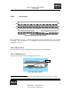
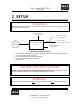
1.4.3 DIGITAL INTERFACE
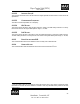
Figure 12 Digital Output Connector
The digital format consists of two 16bit signed values, one for pitch, and the other for yaw. The digital
values are sent as a single 32-bit digital word using the high speed serial peripheral interface (SPI) of the
TMS320VC33 DSP. The digital interface conforms to the low voltage differential signaling (LVDS
1
)
standard.
• Clock Rate: 7.5 Mhz
• Word Output Rate: 21.6Khz
• Bit Width: 133.3ns/bit
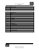
Part Number
Description
DF13 – 10P – 1.25H(50) Board Connector
DF13 – 10S – 1.25C Mating Connector
DF13 – 2630SCFA CRIMP PIN
Pin Number
Description
1 DSP CLK+
2 DSP CLK-
3 DSP FSX0+
4 DSP FSX0-
5 DSP Data-
6 DSP Data+
7 NO CONNECTION
8 INPUT- OPTION
9 INPUT+ OPTION
10 NO CONNECTION
1
American National Standards Institute (ANSI)/Telecommunications Industry Association (TIA)/
Electronics Industries Alliance (EIA)-664-1995 standard specifying the physical layer defining the driver
and receiver characteristics.