
User`s guide
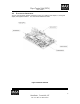

Gyro Control Unit (GCU)
User’s Guide
2
MaxMetrix, Scottsdale, AZ
PN: GCU-2K1-UG:RevI.2 NGC
CONTENTS
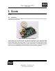
1 Scope ..................................................................................................................................................... 5
1.1 Overview .......................................................................................................................................... 5
1.2 Theory of Operation ......................................................................................................................... 6
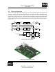
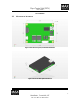
1.3 Mechanical Interface ........................................................................................................................ 7
1.4 Electrical Interfaces .......................................................................................................................... 9
1.4.1 Power Supply Interface .......................................................................................................10
1.4.2 Analog Interface ..................................................................................................................11
1.4.3 Digital Interface...................................................................................................................12
1.4.3.1 Data Format ....................................................................................................................13
1.4.4 USB Interface ......................................................................................................................13
1.4.5 G-2000 Interface .................................................................................................................13
2 SETUP .................................................................................................................................................15
3 APPLYING POWER ...........................................................................................................................16
3.1 LED Status Indicators .....................................................................................................................16
3.1.1 Microcontroller Status .........................................................................................................16
3.1.2 DSP Status ...........................................................................................................................16
4 Performance Analyzer .........................................................................................................................17
4.1 Performance Analyzer (Gyro Setup Program) ................................................................................17
4.1.1 CAL/STATUS TAB ............................................................................................................18
4.1.1.1 Commands ......................................................................................................................18
4.1.1.1.1 Torquer On | Off ......................................................................................................19
4.1.1.1.2 Motor On | Off .........................................................................................................19
4.1.1.1.3 Save Calibration .......................................................................................................19
4.1.1.1.3.1 Path to Save Calibration Files ..............................................................................19
4.1.1.1.4 Send Command Button ............................................................................................19
4.1.1.1.5 Additional Information .............................................................................................19
4.1.1.1.6 Read Values from DSP ............................................................................................19
4.1.1.1.7 Write Values to DSP ................................................................................................19
4.1.1.2 Control Law Parameters .................................................................................................19
4.1.1.2.1 Proportional Gain, K
p
...............................................................................................19
4.1.1.2.2 Integral Gain, K
i
.......................................................................................................20
4.1.1.2.3 Compensator Frequency ...........................................................................................20
4.1.1.2.4 ADC Offset ..............................................................................................................20
4.1.1.2.5 DAC Offset ..............................................................................................................20
4.1.1.3 Read Values from DSP ...................................................................................................20
4.1.1.4 Update Values .................................................................................................................20
4.1.2 The Scope ............................................................................................................................21
4.1.2.1 Channel Enable ...............................................................................................................21
4.1.2.2 Auto Y ranging ...............................................................................................................21
4.1.2.3 Sample Rate ....................................................................................................................21