
User`s guide

Gyro Control Unit (GCU)
User’s Guide
3
MaxMetrix, Scottsdale, AZ
PN: GCU-2K1-UG:RevI.2 NGC
4.1.2.4 Number of Samples ........................................................................................................21
4.1.2.5 Start | Stop .......................................................................................................................22
4.1.2.6 Connect | Disconnect ......................................................................................................22
4.1.3 The Spectrum Analyzer .......................................................................................................23
4.1.3.1 DATA SELECT ..............................................................................................................24
4.1.3.2 Auto-Y ............................................................................................................................24
4.1.3.3 PSDE...............................................................................................................................24
4.1.3.4 Peak Hold Enable ............................................................................................................24
4.1.3.5 Frequency Range ............................................................................................................25
4.1.3.6 Start | Stop .......................................................................................................................25
4.1.4 The Bode Analyzer..............................................................................................................26
4.1.4.1 How it works ...................................................................................................................27
4.1.4.2 Axis .................................................................................................................................28
4.1.4.3 Trace Color .....................................................................................................................28
4.1.4.4 Parameters .......................................................................................................................28
4.1.4.4.1 Start Frequency ........................................................................................................28
4.1.4.4.2 Stop Frequency.........................................................................................................28
4.1.4.4.3 Excitation Amplitude ...............................................................................................28
4.1.4.4.4 Sample Rate .............................................................................................................28
4.1.4.4.5 Duration ...................................................................................................................28
4.1.4.5 Start | Stop .......................................................................................................................28
4.1.5 Notch Filter Adjustments ....................................................................................................29
4.1.5.1 Write to DSP ...................................................................................................................29
4.1.6 Firmware Loader .................................................................................................................31
4.1.6.1 Browse ............................................................................................................................31
4.1.6.2 Load ................................................................................................................................32
4.1.6.3 NO-OP ............................................................................................................................33
4.1.6.4 DSP Entry Point ..............................................................................................................33
4.1.6.5 Autoboot Enable .............................................................................................................33
4.1.6.6 Firmware Release Level .................................................................................................33
4.1.6.7 Troubleshooting the LINK ..............................................................................................33
4.1.7 Manufacturing Report .........................................................................................................34
4.2 Parameter Buttons and Storage .......................................................................................................36
5 SOFTWARE LICENSE .......................................................................................................................37
6 FAQ and Technical Support ................................................................................................................39
6.1 Gyro Setup Software does not respond to commands .....................................................................39
6.2 G-2000 Gyro is unstable after power is applied ..............................................................................39
6.3 Gyro not Caging ..............................................................................................................................39
6.4 Mechanical Dimensions ..................................................................................................................41
6.5 Electrical Specifications ..................................................................................................................41
6.6 Environmental Specification ...........................................................................................................41
FIGURES
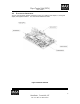
Figure 1 GCU2K1, Gyro Control Unit (GCU)
............................................................................................... 5
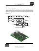
Figure 2 GCU, Block Diagram
....................................................................................................................... 6
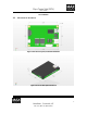
Figure 3 GCU 3-Dimensional Model
............................................................................................................. 6