
User`s manual

Installation
10 User’s Manual - DSP19.2 Fast Poll Modem
Hardware Overview
Front View
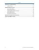
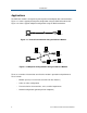
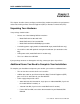
Figure 2-1 shows the front view of the DSP19.2 stand-alone modem. Starting from the left
side, this view shows:
y A set of eight LEDs for modem interface status (see Table 2-6 on page 23)
y A loopback control push-button switch (see Loopback Control Switch on page 23)
Figure 2-1. Front View of the DSP19.2 Modem
Back View
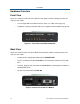
Figure 2-2 shows the back view of the DSP19.2 stand-alone modem. Starting from the left
side, this view shows:
y A 4-wire/2-wire configuration block labeled LEASED LINE
y An RJ-11 modular jack labeled RS-485 for connecting the modem to an RS-485
RTU
y A female, 9-pin RS-232 connector labeled RS-232 for connecting the modem to a
standard DTE (RTU)
y A power connector labeled 10-48V DC
Figure 2-2. Back View of DSP19.2 Modem