
User`s manual

Installation
23 User’s Manual - DSP19.2 Fast Poll Modem
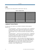
LEDs
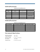
The front panel of the modem provides the LEDs shown in Table 2-5.
Table 2-6. Modem LEDs
LED Color Description
RTS Yellow Request To Send
CTS Yellow Clear To Send
TD Yellow Transmit Data
RD Yellow Receive Data
CD Yellow Carrier Detect
MR Yellow Modem Ready
ALB Red* Analog Loopback
DLB Red* Digital Loopback
* When the modem is in remote loopback, both the ALB and DLB LEDs go ON.
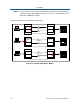
Loopback Control Switch
The front panel of the modem has a push button for initiating the following loopback
diagnostic tests:
y Local analog loopback ⎯ started by pressing the button one time. The ALB LED
should be ON. When a DTE is connected to the RS-232 port of the modem, the
transmit data is loop back to the DTE as receive data. This test will verify the
modem transmitter, receiver, and its RS-232 interface along with the connecting
cable.
y Local digital loopback ⎯ started by pressing the button two times. The DLB LED
should be ON. When a DTE is connected to the RS-232 port of the modem, the
transmit data is loop back to the DTE as receive data. This test will verify the
modem’s RS-232 interface along with the cable attached.
y Remote digital loopback ⎯ set the local modem’s RTS signal to low. Press the
local modem’s diagnostics test button three times. Both the ALB and DLB LEDs
should be ON. Then raise the local modem’s RTS signal to start the test. The
ALB and DLB LEDs of the remote modem should go ON when the modem is
responded to remote digital loopback. This test will verify both modems’
transmitters, receivers, and the leased line