
User`s manual

Contents
v User’s Manual - DSP19.2 Fast Poll Modem
Figures
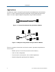
Figure 1-1. Point-to-Point Network Using the DSP19.2FP Modem.........................................8
Figure 1-2. Multipoint Polling Network Using the DSP19.2FP Modem ...................................8
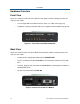
Figure 2-1. Front View of the DSP19.2 Modem ....................................................................10
Figure 2-2. Back View of DSP19.2 Modem...........................................................................10
Figure 2-3. Rack-Mount Module for the DSP19.2-RM Modem Board...................................11
Figure 2-4. DSP19.2 Fast-Poll Stand-alone Modem Board ..................................................13
Figure 2-5. DSP19.2 Fast-Poll Rack-mount Modem Board ..................................................13
Figure 2-6. DSP19.2 Modem Transmission Line Interface ...................................................20
Figure 2-7. Pin Locations on the Modem’s RJ-11C Jack......................................................22
Figure 2-8. Loopback Diagnostic Modes...............................................................................24
Figure 2-9. Back-to-Back Connection to a Second Modem..................................................27
Tables
Table 2-1. Modem Switch Settings .......................................................................................14
Table 2-2. Modem Operating Speed.....................................................................................15
Table 2-3. Transmit Levels....................................................................................................17
Table 2-4. Transmission Line Connector Pin Assignments ..................................................20
Table 2-5. RJ-11C Modular Jack Pin Assignments...............................................................22
Table 2-6. Modem LEDs .......................................................................................................23
Table A-1 Problem Solving ..................................................................................................25
Table B-1. Leased Line Terminal Block Pin Assignments ....................................................27
Table B-2. RS-232 (DTE) Interface.......................................................................................28
Table B-2. RS-485 (DTE) Interface.......................................................................................28