
User Manual

WMTS TRANSCEIVERS
200 PatientNet Operator’s Manual, v1.04, 10001001-00X, Draft
All information contained herein is subject to the rights and restrictions on the title page.
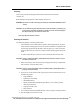
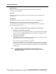
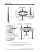
Fig. 92. DT-7000/DT-7001 Controls, I/O Ports, and LED Indicators
Note: *Only Port 1 of the External Serial Device (I/O) is functional. I/O Ports 2, 3
and 4 will be functional in future product releases.
External Serial Devices
(I/O) Ports 3 and 4*
Nurse Call
button
Attendant
Present and
Power buttons
Procedure Alarm
Silence (PAS) button
PAS Status Indicator
Remote Record button
External Serial Devices
(I/O) Ports Status Indicators*
RF, Low Battery,
and Power Adapter
Indicators
Power Connector
Front View
External Serial Devices
(I/O) Ports 1 and 2*
Bottom View