
User guide


DATA-LINC GROUP
5
CCS9000 User Guide
PN 161-09996-003A
rev 9/03
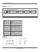
Green Indicates Port 4 is active
Operating Modes
CCS9000/DU Dial-Up
The dial-up remote version is a Trellis Coded Modulation Carrier designed to be used with standard analog telco circuits.
The unit’s unique five digit address is transmitted in standard ASCII code format. The yellow carrier indicator will come
on solid if the address received matches the unit’s. The port that was chosen to connect to will then come on solid
indicating a successful connection. When data is flowing out of the port to the device it is connected to the ‘O’ Data Out
indicator will flash. When data is flowing into the port from the device it is connected to the ‘I’ Data In indicator will flash.
There is an RJ11 connector provided for the carrier line connection, the two center contacts are the only ones used and
are not polarity sensitive. They are the red and green wires with terminal connections on the cable provided with the
remote.
CCS9000/LL Leased Line
The leased line remote version is a Trellis Coded Modulation Carrier designed to be used with conditioned leased or
private lines. Two twisted conductors are all that is needed. Line conditioning is available through Data-Linc Group for
private lines. For local telco leased lines this device is not needed. The unit’s unique five digit address is transmitted in
standard DTMF tones. The recognition of tones can be observed through the amber tone indicator on the front panel it
will light momentarily during the receiving of any DTMF signal. If the tones match the unit’s unique address the yellow
carrier indicator will then come on solid. The port that was chosen to connect to will then come on solid indicating a
successful connection. When data is flowing out of the port to the device it is connected to the ‘O’ Data Out indicator will
flash. When data is flowing into the port from the device it is connected to the ‘I’ Data In indicator will flash. There is an
RJ11 connector provided for the carrier line connection, the two center contacts are the only ones used and are not
polarity sensitive. They are the red and green wires with terminal connections on the cable provided with the remote.
CCS9000/RAD Radio
The wireless model is a 902 to 928 megahertz spread spectrum frequency hopping radio unit. Algorithms utilize up 110
frequencies in hopping patterns that ensure excellent noise immunity and high reliability. The unit’s unique five digit
address is transmitted via RF in standard ASCII code format. The yellow carrier indicator will come on solid if the
address received matches the units. The port that was chosen to connect to will then come on solid indicating a
successful connection. When data is flowing out of the port to the device it is connected to the ‘O’ Data Out indicator will
flash. When data is flowing into the port from the device it is connected to the ‘I’ Data In indicator will flash. There is a
SMA connector provided for the antenna connection. Data-Linc Group strongly suggests that a professional complete the
installation of the antenna and cable. Refer to the documentation included with the antenna/cable and bracket assembly
purchased separately from Data-Linc Group.