
User guide


DATA-LINC GROUP
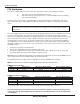
6
PN 161-09996-003A
rev 9/03
CCS9000 User Guide
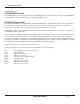
Diagram 1
Led and Connector Locations
There are ten LED indicators on the front panel of the CCS9000/DU and CCS9000/LL, nine on the CCS9000/RAD. From left
to right they are:
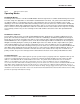
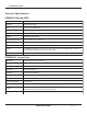
Diagram 2
RS232 Pin Functions and Pin Out
Phone Line
9AV Aux.
Port 5 Port 2 Port 3Port 1 Port 4
SPO I TC 1 2
34
5
32
4
1
9
8
76
Port Connector DB9M
Pin 1 Carrier Detect
Pin 2 Data In
Pin 3 Data Out
Pin 4 N/U
Pin 5 Ground
Pin 6-9 N/U
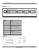
gnikraMnoitcnuF
SrekaepS
PdeilppArewoP
Otrop232-SRfotuogniwolfataD
Itrop232-SRotnigniwolfataD
TetomeRybnoitceteDenoT
CtceteDreirraC
1detceles1troP
2detceles2troP
3detceles3troP
4detceles4troP