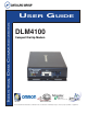
INDUSTRIAL DATA COMMUNICATIONS USER GUIDE DLM4100 Compact Dial-Up Modem It is essential that all instructions contained in the User Guide are followed precisely to ensure proper operation of equipment.
Product User Guide DATA-LINC GROUP PN 161-09977-001B
DLM4100 User’s Manual Operating Instructions The DLM4100 is a compact dial-up modem designed and manufactured to operate in full industrial applications. It is powered with an input voltage range of +8V to +15VDC. A 120VAC to unregulated 12VDC wall transformer power supply has been provided (24VDC versions also available). The operating temperature range of this device is 0° to 70° C. The (ET) Extended Temperature model is rated at -40° to +85° C.
DLM4100 User’s Manual Indicators There are four LED’s displayed out the front panel for status and diagnostics they are as follows: (P) Power Red On indicates that the board is receiving power (C) Carrier Amber On indicates that a connection has been made to another DLM4100 ( I ) Data In Yellow On indicates that data is flowing into the serial port (O) Data Out Green On indicates that data is flowing out to the serial port Since the DLM4100 has been pre-configured at the factory for typical PLC to PC use,
DLM4100 User’s Manual AT Commands A- Answer Command – ATA forces the modem to immediately go off-hook and begin transmitting the answer tone sequence. Bn- Select Communications Standard – ATBn selects the modulation scheme used for connections below 2400 bits per second. n=0 Selects CCITT standards n=1 Selects Bell standards D- Dial Command – Below are the characters accepted in a dialing command.
DLM4100 User’s Manual On- On Line – ATOn switches the modem from the command mode to the data mode. n=0 Return on-line with no retrain n=1 Initiate retrain returning on-line Qn- Reponses – ATQn determines if the modem will issue responses n=0 Send responses* n=1 No responses SR?- Interrogate Register – ATSr? request the current value in register Sr.
DLM4100 User’s Manual &Dn- DTR – AT&Dn determines how the modem will respond to changes to DTR n=0 DTR is ignored by the modem n=1 Enter command mode if DTR revoked n=2 Disconnect if DTR revoked n=3 Soft reset when DTR revoked &Gn- Guard Tone – AT&Gn controls the guard tone produced by the modem n=0 Guard tone disabled n=1 Guard tone disabled n=2 1800 Hz guard tone &Kn- Flow Control – AT&Kn selects the flow control method used by the modem n=0 Disabled n=3 RTS/CTS n=4 XON/XOFF n=5 Transparent XON/XOFF n=6
DLM4100 User’s Manual &Vn- View Configuration Profiles – AT&Vn permits the user to check on the modem’s current configuration n=0 View active profile & user profile 0 n=1 View active profile & user profile 1 &Wn- Store Active Profile – AT&Wn stores the current modem configuration in NVRAM.
DLM4100 User’s Manual \Kn- Break Control – AT\Kn determines how the modem will handle a break signal.
DLM4100 User’s Manual +MS- Select Modulation – AT+MS sets the modulation and available data rates in the format shown below AT+MS= a, b, c, d, e, f a=Modulation type B103- Bell 103 (300 BPS) B212- Bell 212 (1200 BPS) V21- V.21(300 BPS) V22- V.22 (1200 BPS) V22B- V.22bis (1200 or 2400 BPS) V23- V.23 (1200 Tx/ 75 RX or 75 Tx/ 1200 Rx) V32- V.32 (4800 or 9600 BPS) V32B- V.32bis (4800 to 14400 BPS) V34- V.
DLM4100 User’s Manual S3 Carriage Return Character: S3 determines the ASCII character to serve as a carriage return to terminate commands and modem responses. Range: 0 to 127 Units: ASCII Character Default: 13 (carriage return) S4 line Feed Character: S4 sets the ASCII character to act as a line feed character in modem responses. Range: 0 to 127 Units: ASCII Character Default 10 (line feed) S5 Back Space Character: S5 defines the ASCII character used as a back space to edit the command line.
DLM4100 User’s Manual S10 Carrier Off Disconnect Delay: S10 selects how long carrier must be lost before the modem disconnects. Note: if S10 is smaller than the value of S9, the modem will not automatically disconnect on loss of carrier. Range: 1 to 255 Units: 0.1 Seconds Default: 14 S11 Tone Dialing Speed: S10 sets the duration and spacing of the dialing tones. S11 does not affect the pulse dialing rate.
DLM4100 User’s Manual S21 General Bit-Mapped Options: S21 reflects the state of several “AT” commands. Bit 0-2 Not used Bit 3-4 0=DTR ignored (&D0) 1=Enter command mode on DTR off (&D1) 2=Disconnect on DTR off (&D2) 3=Reset on DTR off (&D3) Bit 5 0=DCD always active (&C0) 1=DCD on with carrier (&C1) Bit 6 0=DSR always active (&C0) 1=DSR on when modem ready (&C1) Bit 7 0=No disconnect on space (ATY0) 1=Disconnect on space (ATY1) S22 General Bit-Mapped Options: S22 reflects the stat of several “AT” commands.
DLM4100 User’s Manual S24 Sleep Mode Timer: S24 sets the length of time in seconds that the modem must be idle before entering the low power, sleep mode. When S24 is set to 0, sleep mode is disabled. Range:0 to 255 Units: seconds Default: 0 S27 Pulse Dialing Bit-Mapped Options: S27 reflects the state of several “AT” commands.
DLM4100 User’s Manual S33 XOFF Character: S33 determines the ASCII character to be recognized as XOFF for in-band flow control. Range: 0 to 255 Units: ASCII Character Default: 19 (DC3) S36 LAPM Failure: S36 instructs the modem what to do if the error control negotiations fail.
DLM4100 User’s Manual S41 General Bit-Mapped Options: S41 stores the condition of various “AT” commands. Bit 0-1 0=No data compression (AT%C0) 1=MNP5 data compression (AT&C1) 2=V.42bis data compression (AT&C2) 3=Either MNP5 or V.42bis data compression (AT&C3) Bit 2 6 0 0=No fall back/forward (AT%E0) 1 0=Retrain enabled (AT%E1) 0 1=Fall back/forward enabled (AT%E2) Bit 3-5,7 Not used S46 Data Compression Control: S46 selects whether or not he modem will support data compression with error control.
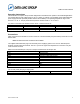
DLM4100 User’s Manual Result Code Digits 0 1 2 3 4 5 6 7 8 9 10 11 12 13 14 15 16 17 18 19 22 23 33 35 40 44 45 46 47 48 49 50 51 52 53 54 55 56 57 P/N 161-09977-001B Verbose OK CONNECT RING NO CARRIER ERROR CONNECT 1200 NO DIAL TONE BUSY NO ANSWER CONNECT 600 CONNECT 2400 CONNECT 4800 CONNECT 9600 CONNECT 7200 CONNECT 12000 CONNECT 14400 CONNECT 19200 CONNECT 38400 CONNECT 57600 CONNECT 115200 CONNECT 75TX/1200RX CONNECT 1200TX/75RX FAX DATA +MRR: 300 +MRR: 1200/75 +MRR: 75/1200 +MRR: 1200 +MRR: 2400 +M
DLM4100 User’s Manual 58 59 61 62 63 64 66 67 69 70 77 78 79 80 81 84 91 134 135 136 137 138 139 140 141 142 +F4 P/N 161-09977-001B +MRR: 28800 CONNECT 16800 CONNECT 216000 CONNECT 24000 CONNECT 26400 CONNECT 28800 +DR: ALT +DR: V42B +DR: NONE +ER: NONE +ER: LAPM +MRR: 31200 +MMR: 33600 +ER: ALT +ER: ALT CELLULAR CONNECT 33600 CONNECT 31200 +MCR: B103 +MCR: B212 +MCR: V21 +MCR: V22 +MCR: V22B +MCR: V23 +MCR: V32 +MCR: V32B +MCR: V34 +FCERROR 28800 BPS carrier received 16800 BPS connection 21600 BPS conn
DLM4100 User’s Manual Technical Support Data-Linc Group maintains a fully trained staff of service personnel who are capable of providing complete product assistance. They can provide you with technical and application troubleshooting, spare parts and warranty assistance. Our technical staff is based in Redmond, Washington USA and may be reached at (425) 882-2206 or email support@data-linc.com.