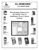
DL-WINDOWS™ 345 Bayview Avenue Amityville, New York 11701 For Sales and Repairs 1-800-ALA-LOCK For Technical Service 1-800-645-9440 Publicly traded on NASDAQ V4.0 USER'S GUIDE Symbol: NSSC © ALARM LOCK 2010 DK3000 OI237I 11/10 Downloading Software for the Trilogy® Line of Standalone Access Control Systems PDK3000 ETDL PDL3500 PDL4500 - "RESIDENCY" LOCK DL3500 DL4500 - "RESIDENCY LOCK" DL3000 DL4100 - "PRIVACY LOCK" DL-WINDOWS™ V4.
Table of Contents DL-Windows Features..............................................................................................................................................................3 Supported Products .................................................................................................................................................................4 Product Communication Examples ......................................................................................................
DL-Windows Features Basic Functions When installed on an IBM compatible desktop or notebook computer, DL-Windows can provide the following functions: • Create a new Lock Program • Edit an existing Lock Program • Send a Lock Program to a lock • Receive a Lock Program from a lock • Retrieve an Audit Trail (Event Log records) from a lock • Configure an AL-DTM to transfer data to multiple locks • Read ProxCards® using the ProxCard® Reader (ALPRE) • Communicate wirelessly to Networx™ locks (see the Networx™ syst
Supported Products PDL3000 / PDL3500 2000 User Codes/ProxCards® or ProxKey® keyfobs, 500 Schedules, 40,000 Audit Trail Events. Refer to WI1021 for more information on features. DL-Windows also supports the similar PDL3500 mortise lock. DK3000 / PDK3000 Relay-only locking device, 2000 Users, 500 schedules, 40,000 Audit Trail events. The PDK3000 adds Prox capability. DL3000 / DL2800 300 User Codes, 150 Schedules, 1600 Audit Trail Events. Refer to OI224 for more information on DL3000 features.
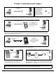
Product Communication Examples AL-PCI2 CABLE CONNECT TO SERIAL PORT (COM 1-4) If your computer does not have a serial COM port (DB9 male) available, you can plug your AL-PCI2 cable into a special USB to RS232 cable. Order part MX1130 for the USB to RS232 cable only, or ALPCI2U for both the USB to RS232 cable and an AL-PCI2 cable.
Overview Why use User Codes? With ordinary door locks, the need to make physical copies of metal keys and distributing them can be a huge organizational and financial task -- and what will you do if someone causes a security breach by accidentally losing their key? The answer lies in the advantage of "firmware". The firmware can be programmed (and re-programmed again and again) to suit your changing requirements. No more metal keys to distribute...
Terminology DL-Windows DL-Windows is a computer program that allows you to program your ALARM LOCK T3 Security Lock. You do not need DL-Windows to program your lock, but it makes programming much faster and easier. With DL-Windows, you can quickly create Lock Profiles (software that makes the lock perform its many functions) add multiple Users (who have access), add ProxCards® and ProxKey® keyfobs, retrieve event logs, and create Schedules.
Terminology (cont'd) level required to access the particular Function. (The higher the level number, the more programming tasks the User is allowed, with Master allowing all tasks). In this manual, Programming Levels are abbreviated as follows: M = Master, 4 = Installer, 3 = Manager, 2 = Supervisor, 1 = Print Only Users User Numbers (User Number = Location Number = User Location = Slot in Lock) User Numbers are used and are significant within each individual lock only.
DL-Windows Buttons The DL-Windows toolbar (above) allows you to open the screens and dialogs you will need to program your lock. It may be helpful to open each screen on your computer as you read. From left to right, they are as follows: Comm - Opens the Receive from Lock dialog or the Send to Lock dialog. Allows for direct communication between DL-Windows and the locks.
DL-Windows Main Menu Menu System and Shortcut keys The sub-menus within the DL-Windows Main Menu bar can be activated by clicking the mouse or via shortcut keys. They are as follows: Window Menu (Alt + W) Cascade - (Can also press F5) Lock Data Schedules File Menu (Alt + F) Exit - Quits and closes the application.
Quick Start Checklist You have installed the locks in the doors. Now you want use DL-Windows to program the locks. What are the main steps? OPENING STEPS ❒ 1. Install the DL-Windows software into your computer (see page 12) ❒ 2. Create a new Account and add locks (see page 15) ❒ 3. Add Users (and other data) using Global Users screen (see page 16) ❒ 4. Enroll ProxCards (for "PDL" and "PL" proximity locks only) (see page 17) ❒ 5. Add Schedules and TimeZones (see page 20) ❒ 6.
DL-Windows Software Installation Installing DL-Windows Software Note: Uninstall any previous version of DLWindows before Installing DL-Windows. Account data associated with previous installations will remain intact, with the exception of Prox devices (see warning below). Use the Update Database utility on databases created using prior versions of DLWindows. Please read the readme.txt file for the latest information about DL-Windows. See page 6 for DL-Windows System Requirements. 1.
Upgrading From a Previous Version of DL-Windows NOTE: This section applies only to Accounts and locks created with previous versions of DL-Windows. For new Accounts, please ignore the following instructions. When selecting your database files, the Files of type pull-down menu lists two file types: • New DL-Windows Index files • Old DL-Windows Index files The Old file type is listed as AL3000.MDB and the New file type is listed as AcctList.adf.
DL-Windows Security Features Security Features in DL-Windows Change an Existing Password The DL-Windows software provides security and protection features to restrict unauthorized persons from accessing your DLWindows program. When starting DL-Windows, a user name and password are required to access the program. Creating user names requires a User Type be selected, (either Operator or Administrator). This User Type determines the range of tasks allowed within DLWindows.
Create a New Account and Add Locks Create a New Account Press the Global button. The Global Users screen will appear (below). Programming of User Codes, Programmable Features and Schedules can now begin. Note: The screens that display on StartUp can be selected under Options (press the Opt button). Right-click in this white area. Select New Account. For new installations, a popup appears (shown above).
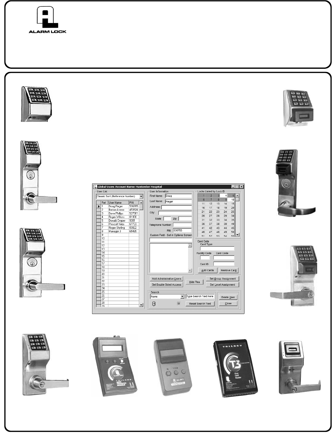
Add Users with the Global Users Screen Overview Select a Range of Users The Global Users screen is used to enter all User information. Users can be assigned to specific locks and assigned to Groups within locks. All Basic Users are entered here as well as the Level Assignment for DL3000/2800 locks. User lists can be imported from other DLWindows Accounts or from comma delimited formatted lists. Administrative Users can be accessed through the Global Users screen via the Add Administrative Users button.
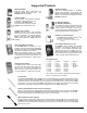
Enroll ProxCards® with the AL-PRE CONNECT DB9 CABLE TO COMPUTER SERIAL PORT (COM 1-4) DOUBLE-ENDED MINI BANANA PLUG CONNECTOR DB9 to DB9 Serial Cable (supplied) IBM COMPATABLE LAPTOP OR DESKTOP PC NOTE: OBSERVE TAB DIRECTION WHEN INSERTING CABLE INTO AL-PRE AND LOCK AL-PRE PROXCARD READER/ ENROLLER ® PDL3000 LOCK ® ® Enroll ProxCards and ProxKey keyfobs quickly into DL-Windows, then transfer this new ProxCard data from the computer through the AL-PRE to the lock. For PDL series locks only.
6. 7. Select the Prox card type from the “Card Type” drop down Note: All proximity information for the selected User will be rebox. moved from all locks in the Account. When the warning dialog apCard Type Dropdown Box: pears, press Yes to delete the proximity information. There are a few pre-existing Card Types. If your Card Type is not listed or is unknown, select the “Unknown” type.
"User Defined" Type In the Global Users screen, in the ProxCard Data area, press the Add Cards button. The Prox Card Enrolling dialog opens. If you wish to enroll a proximity credential (card and/or fob) that does not fit the standard types listed in the Card Type pull-down list, or if you wish to enter all proximity data manually, select User Defined from the Card Type pull-down menu.
Creating Schedules and TimeZones Schedules are customized by the use of two screens. The first is the Schedule - Timezone screen. Click the Sched button or click Window, Schedules to open. is very useful in that it presents the "complete picture", displaying all parts of the schedule, for each schedule you have to work with. Working with Schedules Note: Schedules are local to the lock and not shared, while TimeZones are global and will appear in all lock configurations within an Account.
Send/Receive Information to/from the Lock Communication Overview There are several methods for sending data to (or receiving data from) a lock. One method is Direct PC communication to the lock and the other method is to use the AL-DTM-III (Data Transfer Module). When using a PC for communication, several options may be used for sending and receiving data. The data transmission may be segmented into User information, Schedules, Features Group Status and Time/ Date or All segments may be sent at one time.
Sending Data directly to the Lock from the PC Connect the AL-PCI2 cable's DB-9 connector to a Serial Port at the rear of your PC (if your computer does not have an available Serial Port, a USB adapter is available – refer to Product Communication Examples section in this manual). Connect the other end of the ALPCI2 cable to the lock, observing tab direction (tab to black socket). The comm port setup is covered in the rear of this manual. 1.
Receiving Data from the Lock Receiving data from the lock is handled in a similar way as sending data to the lock. You can selectively decide what you want to receive from the lock (i.e. User Data, Schedules, Features or the Event Log). Use "Receive from Lock" to review changes to Users made at the lock. Note: To receive data wirelessly, see OI352.
Receive Event Log When receiving the Event Log from the lock into DL-Windows, the log can be viewed in the Event Log Viewer screen. Note: By default only the last 50 events are received from the lock. To receive more events, select the number of events in the Max. Event Log Length pull-down list (as shown in the image below). When using a PC, the complete log (up to a maximum of 40,000 events) can be received.
Configure the AL-DTM The AL-DTM may be configured for Foreign Language support and the Door Select feature (see below). Warning: Entering the following Configuration Mode will clear all data (lock information) from memory. 1. 2. Place AL-DTM into PC COMM MODE. If not already in PC COMM MODE, press green button to enter this mode. PC COMM MODE . . . on each press of the green button; when SLEEP THEN POWER DOWN appears, press and hold the green button to exit Configuration Mode.
Send Data from DL-Windows to the AL-DTM Introduction When computers cannot be transported or when electrical power is not available, the hand-held AL-DTM device acts as a go-between-it allows the transfer of lock data from the computer (through the ALDTM) and to the lock, or in reverse (from the lock through the ALDTM back to the computer). An AL-PCI2 cable is required when transferring from your PC to the AL-DTM.
Send Data from the AL-DTM to the Lock Transferring Data from AL-DTM to Locks for the first time 1. Connect the AL-DTM to the Lock. Connect the double-ended banana plug into the AL-DTM and into the lock that is to be programmed (observing proper tab direction). 2. The AL-DTM will display the LOCK MODE screen, press the green button to toggle through the following screens: PC COMM MODE 11/28/06 02:23PM LOCK MODE YES NO DOOR SELECT MODE YES NO 3.
Receive Event Logs with the AL-DTM After all lock programming has been completed, the AL-DTM can be easily re-configured to retrieve event logs. Door 0001, LOG Packet 1. In DTM Support screen click in the DTM Function column for the selected lock, click the down arrow and the pull-down menu will display. Select the "Receive Log" Function. Lock’s time and date, updated. Multiple locks can be programmed to receive logs by right clicking in the DTM Function column and select "Change All to 'Receive Log.
"Global Users" Screen - Field and Button Definitions One building may contain many locks. To add the same User to each lock again and again can quickly become tedious. The solution is the Global Users screen. The Global Users screen allows you to enter a User's name and information ONCE, then quickly and easily add this User to any lock (up to 2000) in the Account, as well as designate the User's specific Location Number (within each lock) and User Code (Pin Number).
"Set Double Sided Access" Entry Side Selection The Alarm Lock Trilogy 5200 series and 5300 series locks are double-sided to allow control entry and exit. Since either side of the door is "protected", the idea of an "inside" or "outside" may not always apply. The installation instructions for the 5300 series locks differentiate between the two sides of the lock by using the terms "primary" side and "secondary" side.
"Global Users" Screen - Right-Click Menu Right-click in the "User List" area of the Global Users Screen opens a right-click menu; each item is detailed below. To select multiple Users, press and hold the CTRL keyboard key, click the right arrow ("►") located to the left of the User Name. Single-click the right arrow ("►") to select only one User. Right-Click Menu Highlight a name or names (or an empty slot) and rightclick to open the menu shown at right.
"Administrative Users" Screen - Field Definitions The Administrative Users screen is used assign Users to the administrative locations within the locks, determining their Programming Levels and therefore defining the range of programming tasks a User is allowed to perform. Press the Add Administrative Users button (on the Global Users screen) to Access the Administrative Users screen. User Name Names appear in this column when First Name and Last Name fields in this screen are populated.
"Lock Data" Screen - Field Definitions The Lock Data screen is used to view User Codes, Group Associations and Program Levels inside individual locks. 9Quick Tip: After entering Users and assigning Users to Location Numbers ("Slots") by using the Global Users screen (see page 29), use the Lock Data screen (shown at right) to view and confirm the User Location assignments made inside each individual lock. User Locations determine Programming Levels for each lock.
"Event Log Viewer" Screen - Field Definitions The Event Log Viewer screen is used to view each event (also called the "Audit Trail"). Note: In the Event Log Viewer screen, each column heading (Date, Time, etc.) can be clicked to sort its data. Date The date the event occurred (MM/DD/YY). Click the heading to sort its contents. Time Export Log Click the Export Log button and two selections appear (as shown below): You can click either Export Log to Text File or Export Log to CSV File.
"Programmable Features" Screen - Options tab The Programmable Features screen is used to program lock options and a variety of programmable Features. Group 2 Toggles Passage Mode A Group 2 User will toggle passage mode (lock is unlocked). Caution! The consequences of accidentally selecting this option can cause a security breach! (Not applicable to the DL2800/DL3000). Group 2 Enables and 3 Disables Passage Mode A Group 2 User will put door into passage mode (lock is unlocked).
"Programmable Features" Screen - Customize DST The Programmable Features screen, Options tab will vary depending the lock model, as shown below. Some locks require either DST be disabled or customized, other locks also allow the selection of pre-set DST modes for the varied DST adjustments throughout the world. See below for details regarding the Custom DST button and customizing the DST start and end dates.
"Programmable Features" Screen - Relay Functions tab The Features screen is used to program Relay Functions and other programmable Features. If programmed, one or more of the following relay Functions will activate an external Relay for an interval of 3 seconds, if the condition is met. If Relay follows Lock/Unlock Status is selected, the relay will remain activated as long as the door is unlocked. Select any of the Functions below to Activate the Relay Output (more than one may be selected).
"Programmable Features" Screen - Remote tab This screen is used to program Remote Input Functions. Note: Remote Disabled Lock, Forced Lock Follows Remote or Forced Unlock Follows Remote should only be used with external power to the lock. Note: These Remote Release Functions are not available for use with the wireless Networx™ system. Select one of the Remote Input Functions below. Remote Release (Momentary) Remote input is enabled and will cause the door to momentarily unlock.
"Programmable Features" Screen - 4000 Series tab These screens are used to program the Residency/Privacy options and features for the 4000 Series locks. The screens below display the DLWindows screen defaults (which also reflect the "out of box" factory default programming). Shown below (left) a PDL4100 ("Privacy") lock and (right) a PDL4500 ("Residency") lock. Note: DL locks do not provide PROX access, therefore the DL lock screens do not reference PROX options.
"Schedule-TimeZone" Screen - TimeZones Area This screen consists of two parts--the TimeZones area (top) and the Schedule Entry area (bottom). The TimeZones area is used to program the time the event(s) will occur, and the Schedule Entry area is used to create events that can be linked to the times created in the TimeZones area. This page will focus on the TimeZones area. See next page for the Schedule Entry area.
"Schedule-TimeZone" Screen - Schedule Entry Area This screen consists of two parts--the TimeZones area (top) and the Schedule Entry area (bottom). TimeZones area is used to program the time the event(s) will occur, and the Schedule Entry area is used to create events that can be linked to the times created in the TimeZones area. This page will focus on the Schedule Entry area. See previous page for the TimeZones area. Schedule Entry Area Event Number An Event Number is assigned to each scheduled event.
"Schedule View" Screen - Program Field Definitions The Schedule View screen combines the times created in the Schedule-TimeZone screen. The Schedule View screen displays schedules (with their event time information) listed in separate rows. In addition, schedules received from locks are viewed only in the Schedule View screen. Notes on the Schedule View screen: The Schedule View screen is defaulted as a read-only screen. Editing events from this screen is not recommended.
"Options" Screen - Program Field Definitions The Options screen allows you to select Account and DL-Windows preferences. Send Schedule from Schedule View (supervisory) When schedules are received from locks into DL-Windows, they can only be viewed in the Schedule View screen.
Exporting and Importing Data Exporting Data Tools > Export Active Account to CSV This feature exports all User data from a DL-Windows Account and saves the data to a .CSV (comma separated values file) file. The .CSV file can then be imported into another Account using DL-Windows. Click Tools, Export Active Account to CSV on the menu toolbar to export data. For each .CSV file, each line in the file is one entry, and the fields in each entry are separated by commas. Exported .
Transferring Account Files Between PC's We recommend using a USB drive flash memory card when transferring DL-Windows Account files from one computer to another. To ensure a successful transfer, both computers must correctly operate with USB drive flash memory cards before performing this procedure. DL-Windows must not be running on either system. Note: The Tools, Import a Single ADF Account File menu feature used in the procedure below is only supported by DL-Windows versions 3.5.5 and greater.
"DTM 3 Support" Screen - Program Field Definitions The DTM Support screen is used to configure an AL-DTM to transfer data to or from multiple locks. 9Quick Tips: Note: RIGHT click on the DTM Function column, and select desired action: For every new lock that is added, the DTM screen will automatically use the next available Door Number in the selected DTM Configuration. For example, in the screen image at left, the next lock that will be added (for "DTM Config 1") will be Door Number 2.
AL-DTM Specifications AL-DTM - Data Transfer Module Data Transfer Modules allow the transfer of lock programs and other data between DL-Windows software and Alarm Lock locking devices. Currently, the latest software inside Alarm Lock’s Data Transfer Modules is AL-DTM-III, and this version software (or later) is used exclusively with DL-Windows 3.5.X (or later).
Compact and Repair the Database - Backup Accounts Compact and Repair DataBase Maintaining the DL-Windows DataBase is accomplished via the Tools menu. You can export, import and compact/repair the Account information contained in the DataBase. Maintaining the database on a regular basis will reduce the size of the database and improve the reliability of communications between the lock and DL-Windows.
Foreign Language Support Changing the Default Language On the toolbar, click Opt and the Options dialog opens (see below). Additional languages are available in the Select Language drop-down menu. Select the desired language. Editing an Existing Language From the toolbar click Tools, Edit Language's. The Language Translation screen will appear. Note: English cannot be Edited. You must close and restart DL-Windows for the language changes to take effect (press OK to close the popup, shown below).
Advanced Programming (Holiday Example) Programming Schedules with Suppression Follow the steps below to download a schedule with suppression (an exception that "suppresses" the general rule). 1. Enter the time for which the event is to be scheduled in the top (the TimeZones area) of the Schedule-TimeZone screen. In the example below, a general daily unlock event is programmed to occur every Monday - Friday from 8:00 AM to 5:00 PM ("TimeZone 1"). 3.
Advanced Programming--Group 1 Activated Events It is convenient for large numbers of similar Users to be grouped together. Placing Users into Groups (by assigning them specific User Numbers) allows large numbers of Users to be controlled all at once rather than individually--saving time. In the following examples, Users who are members of Group 1 are allowed to activate special lock features or other Groups of Users.
Appendix B A AL-DTM Communications with the PL3000 locks Function Card # 2 Initiates AL-DTM Communications (User 299) The AL-DTM can be used to transfer Lock Programs (and other data) between DL-Windows and PL3000 locks. When computers cannot be transported or when electrical power is not available, the hand-held AL-DTM acts as a go-between-it allows the transfer of lock data from your PC (through the AL-DTM) to the lock, or in reverse (from the lock through the AL-DTM back to your PC).
Appendix B A AL-DTM Communications with the PL3000 locks (cont'd) IMPORTANT NOTE: When programming is sent from DL-Windows (or an AL-DTM) to the lock, Function Cards 1, 2, 8, and 9 will be overwritten with the existing data in DL-Windows for the User Locations 298, 299, 297 and 300, respectively.
Glossary ACCESS = Entry into a restricted area. AMBUSH = A special Code entered at the keypad when the User is forced to unlock a device. The device unlocks but sends a silent alarm with no indication at the keypad. Can be used to trip a relay, to alert security, or trip a silent alarm on a Burglary Control Panel. AUDIT TRAIL = A date/time stamped log of previous lock events. BURGLARY CONTROL PANEL = Provides local alarm and remote communication to request security for burglary/break-in.
Glossary (cont'd) • KEYPAD LOCKOUT = Keypad is programmed to lockout Users, for a specified period of time, when a specified number of invalid User Codes are entered. • KEYPAD PROGRAMMING = Ability to program the lock through the keypad. KEYPRESS = Pressing a button on the Lock’s Keypad. LEVEL ABILITY = Predefined User Types (such as Master, Installer, Manager, Supervisor, and Print Only User) have specific abilities to program and/or control the lock. entering their USER CODE, followed by the [;] key.
ALARM LOCK LIMITED WARRANTY ALARM LOCK SYSTEMS, INC. (ALARM LOCK) warrants its products to be free from manufacturing defects in materials and workmanship for 24 months following the date of manufacture. ALARM LOCK will, within said period, at its option, repair or replace any product failing to operate correctly without charge to the original purchaser or user.