Specification E.9 1/7 Version: /PWFNCFr 20 Data Modul AG - www.data-modul.
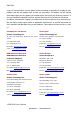
EMX-PNV FCC Statement THIS DEVICE COMPLIES WITH PART 15 FCC RULES. OPERATION IS SUBJECT TO THE FOLLOWING TWO CONDITIONS: (1) THIS DEVICE MAY NOT CAUSE HARMFUL INTERFERENCE. (2) THIS DEVICE MUST ACCEPT ANY INTERFERENCE RECEIVED INCLUDING INTERFERENCE THAT MAY CAUSE UNDESIRED OPERATION. THIS EQUIPMENT HAS BEEN TESTED AND FOUND TO COMPLY WITH THE LIMITS FOR A CLASS "A" DIGITAL DEVICE, PURSUANT TO PART 15 OF THE FCC RULES.
User’s Manual otherwise specified. Applications that are described in this manual are for illustration purposes only. Avalue Technology Inc. makes no representation or warranty that such application will be suitable for the specified use without further testing or modification. Life Support Policy Avalue Technology’s PRODUCTS ARE NOT FOR USE AS CRITICAL COMPONENTS IN LIFE SUPPORT DEVICES OR SYSTEMS WITHOUT THE PRIOR WRITTEN APPROVAL OF Avalue Technology Inc. As used herein: 1.
EMX-PNV If you still cannot find the answer, gather all the information or questions that apply to your problem, and with the product close at hand, call your dealer. Our dealers are well trained and ready to give you the support you need to get the most from your Avalue’s products. In fact, most problems reported are minor and are able to be easily solved over the phone. In addition, free technical support is available from Avalue’s engineers every business day.
User’s Manual Product Warranty Avalue warrants to you, the original purchaser, that each of its products will be free from defects in materials and workmanship for two years from the date of purchase. This warranty does not apply to any products which have been repaired or altered by persons other than repair personnel authorized by Avalue, or which have been subject to misuse, abuse, accident or improper installation.
EMX-PNV Contents 1. Getting Started ............................................................................................................ 8 1.1 Safety Precautions .................................................................................................... 8 1.2 Packing List ............................................................................................................... 8 1.3 1.4 Document Amendment History .......................................................................
3.4 User’s Manual Getting Help ............................................................................................................ 35 3.5 In Case of Problems................................................................................................ 35 3.6 BIOS setup .............................................................................................................. 36 3.6.1 Main Menu and System information .......................................................................
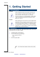
EMX-PNV 1. Getting Started 1.1 Safety Precautions Warning! Always completely disconnect the power cord from your chassis whenever you work with the hardware. Do not make connections while the power is on. Sensitive electronic components can be damaged by sudden power surges. Only experienced electronics personnel should open the PC chassis. Caution! Always ground yourself to remove any static charge before touching the CPU card. Modern electronic devices are very sensitive to static electric charges.
User’s Manual 1.3 Document Amendment History Revision 1 st Date Comment August 2011 Initial Release EMX-PNV User’s Manual 9 Data Modul AG - www.data-modul.
EMX-PNV 1.4 Manual Objectives This manual describes in detail the Avalue Technology EMX-PNV Motherboard. We have tried to include as much information as possible but we have not duplicated information that is provided in the standard IBM Technical References, unless it proved to be necessary to aid in the understanding of this board. We strongly recommend that you study this manual carefully before attempting to interface with EMX-PNV series or change the standard configurations.
User’s Manual 1.5 System Specifications System CPU Onboard Intel PNV-D DC D525 (EMX-PNV-D525) BIOS AMI EFI BIOS (8Mbit SPI) System Chipset ICH8M I/O Chip Winbond 83627DHG System Memory 1 x 204-pin SODIMM 4GB DDR3 800MHz SDRAM(EMX-PNV-D525) SSD One CompactFlash Type I/II Socket Watchdog Timer Reset: 1 sec.~255 min. and 1 sec. or 1 min./step Monitoring CPU temperature and cooling fan status.
EMX-PNV Ethernet LAN1 Intel® 82583V PCI-E Gigabit LAN LAN2 Intel® 82583V PCI-E Gigabit LAN Mechanical & Environmental Power Requirement ATX/ AT Operation Temperature 0~60°C (32~140°F) Operating Humidity 0%~90% relative humidity, non-condensing Size ( L x W ) 6.69" x 6.69" (170 mm x 170 mm) Weight 0.88lbs (0.4Kg) 12 EMX-PNV User’s Manual Data Modul AG - www.data-modul.
User’s Manual 1.6 Architecture Overview – Block Diagram The following block diagram shows the architecture and main components of EMX-PNV. EMX-PNV User’s Manual 13 Data Modul AG - www.data-modul.
EMX-PNV 2. Hardware Configuration 14 EMX-PNV User’s Manual Data Modul AG - www.data-modul.
User’s Manual 2.1 Product Overview EMX-PNV User’s Manual 15 Data Modul AG - www.data-modul.
EMX-PNV 2.2 Installation Procedure This chapter explains you the instructions of how to setup your system. 1. Turn off the power supply. 2. Insert the SODIMM module (be careful with the orientation). 3. Insert all external cables for hard disk, floppy, keyboard, mouse, USB etc. except for flat panel. A CRT monitor must be connected in order to change CMOS settings to support flat panel. 4. Connect power supply to the board via the ATXPWR. 5. Turn on the power. 6.
User’s Manual 2.2.1 Main Memory EMX-PNV provides 1x 204 SODIMM and supports up to DDR3 800MHz SDRAM. The total SODIMM maximum memory size is 4GB. Make sure to unplug the power supply before adding or removing SODIMMs or other system components. Failure to do so may cause severe damage to both the board and the components. Locate the SODIMM socket on the board. Hold two edges of the SODIMM module carefully. Keep away of touching its connectors.
EMX-PNV Firmly press the modules into the socket automatically snaps into the mounting notch. Do not force the SODIMM module in with extra force as the SODIMM module only fit in one direction. Mounting Notch Notch Key Ejector Tab 204-pin DDR3 SODIMM To remove the SODIMM modules, push the two ejector tabs on the slot outward simultaneously, and then pull out the SODIMM module.
User’s Manual 2.3 Jumper and Connector List You can configure your board to match the needs of your application by setting jumpers. A jumper is the simplest kind of electric switch. It consists of two metal pins and a small metal clip (often protected by a plastic cover) that slides over the pins to connect them. To “close” a jumper you connect the pins with the clip. To “open” a jumper you remove the clip. Sometimes a jumper will have three pins, labeled 1, 2, and 3.
EMX-PNV Connectors Label Function Note BT1 Battery slot connector CF1 CF card slot connector CN1 Speaker out connector 4 x 1 wafer, pitch 2.0mm CN2 USB connector 4 & 5 5 x 2 header, pitch 2.54 mm CN3 USB connector 6 & 7 5 x 2 header, pitch 2.54 mm CN4 SPI connector 3 x 2 header, pitch 2.0 mm CN5 Serial port 4 connector 5 x 2 header, pitch 2.54 mm CN6 LCD inverter connector 5 x 1 wafer, pitch 2.0mm CN7 Serial port 3 connector 5 x 2 header, pitch 2.
User’s Manual 2.4 Setting Jumpers & Connectors 2.4.1 Clear CMOS (JBAT1) Protect* Clear CMOS * Default 2.4.2 Miscellaneous setting connector (JFTP1) Signal PIN PIN Signal 1 2 SB_LED+ 3 4 GND +3.3V 5 6 HDD_LED 7 8 9 10 PWR_LED+ 11 12 GND 13 14 Open: AT 15 16 Short: ATX AUX TIN BUZZER * Default Note: AUXTIN is usually a port you can add an RESET auxiliary sensor to, to monitor HDD or Chipset temperatures. PWRBTN EMX-PNV User’s Manual 21 Data Modul AG - www.data-modul.
EMX-PNV 2.4.3 Serial port 3/ 4/ 2/ 1 pin 9 signal select (JP1/ JP2/ JP3/ JP4) JP2/ 3/ 4 JP1 JP3 JP4 Ring* Ring* JP1 JP2 +5V +5V +12V +12V * Default 2.4.4 Serial Port 2 Connector in RS232/422/485 (JP5) RS232* Signal RS485 PIN PIN RS422 Signal RXD232 1 2 RXDB RXD485 3 4 RXDB RXD422 5 6 RXDB 22 EMX-PNV User’s Manual Data Modul AG - www.data-modul.
User’s Manual 2.4.5 Serial Port 2 Connector in RS232/422/485 (JP6) RS-422 RS-232* *Default Note: COM2 is available in RS-232 mode by RS-485 Signal PIN PIN Signal DCD#B 1 2 RXDB CM2-1 3 4 CM2-2 485TX- 5 6 422RX+ TXDB 7 8 DTR#B CM2-3 9 10 CM2-4 485TX+ 11 12 422RX- default setting. For using COM2 in 422/485 Mode, please adjust both JP5 and JP6 with corresponding Jumper settings. 2.4.6 ATX power connector (PWR1) Signal PIN PIN Signal +3.3V 11 1 +3.3V -12V 12 2 +3.
EMX-PNV 2.4.7 Speaker out connector (CN1) 2.4.8 Signal PIN AMP_OUT_LP 1 AMP_OUT_LN 2 AMP_OUT_RN 3 AMP_OUT_RP 4 USB connector 4 & 5/ 6 & 7 (CN2/ CN3) Signal CN2 CN3 PIN PIN Signal +5V 1 2 GND P4-/P6- 3 4 GND P4+/P6+ 5 6 P5+/P7+ GND 7 8 P5-/P7- GND 9 10 +5V 24 EMX-PNV User’s Manual Data Modul AG - www.data-modul.
User’s Manual 2.4.9 SPI connector (CN4) Signal 2.4.10 PIN PIN Signal +3.3V 1 2 GND SPI_CS0# 3 4 SPI_CLK SPI_SO 5 6 SPI_SI Serial port 4/ 3 connector (CN5/ CN7) CN5 CN7 Signal PIN PIN Signal DCD 1 2 RxD TxD 3 4 DTR GND 5 6 DSR RTS 7 8 CTS RI 9 10 NC EMX-PNV User’s Manual 25 Data Modul AG - www.data-modul.
EMX-PNV 2.4.11 LCD backlight brightness adjustment (VR1) Signal PIN +5V 1 BRIGHT 2 GND 3 Variation Resistor (Recommended: 4.7KΩ, >1/16W) 2.4.12 LCD Inverter Connector (CN6) Signal PIN +5V 5 BRIGHT 4 LBKLT_EN 3 GND 2 +12V 1 Note: For inverters with adjustable Backlight function, it is possible to control the LCD brightness through the VR signal controlled by VR1. Please see the VR1 section for detailed circuitry information 26 EMX-PNV User’s Manual Data Modul AG - www.data-modul.
User’s Manual 2.4.12.1 Signal Description – LCD Inverter Connector (CN6) Signal Signal Description BRIGHT Vadj = 0.75V ~ 4.25V (Recommended: 4.7KΩ, >1/16W) LBKLT_EN LCD backlight ON/OFF control signal 2.4.13 2.4.14 CD-ROM Audio Connector (CN8) Signal PIN R 4 GND 3 L 2 GND 1 Front audio connector (CN9) Signal PIN PIN Signa MIC2_L 1 2 GND MIC2_R 3 4 +3.3V LINE2_R 5 6 MIC2_JD SENSE_B 7 LINE2_L 9 10 LINE2_JD EMX-PNV User’s Manual 27 Data Modul AG - www.data-modul.
EMX-PNV 2.4.15 General purpose I/O connector (DIO1) Signal PIN PIN Signal DI0 1 2 DO0 DI1 3 4 DO1 DI2 5 6 DO2 DI3 7 8 DO3 DI4 9 10 DO4 DI5 11 12 DO5 DI6 13 14 DO6 DI7 15 16 DO7 SMB_CLK 17 18 SMB_DAT GND 19 20 +5V 28 EMX-PNV User’s Manual Data Modul AG - www.data-modul.
User’s Manual 2.4.16 CPU/System fan connector (FAN1/FAN2) FAN1 (CPU_FAN) FAN2 (SYS_FAN) FAN1 FAN2 2.4.17 Signal PIN GND 1 +12V 2 FANIN 3 VGA power connector (JVGA1) Signal PIN PIN Signal GND 10 9 GND +12V 8 7 +12V +12V 6 5 +12V +3.3V 4 3 +3.3V +5V 2 1 +5V EMX-PNV User’s Manual 29 Data Modul AG - www.data-modul.
EMX-PNV 2.4.18 2.4.19 VGA connector (JVGA2) Signal PIN PIN Signal HS 10 9 VS DAT 8 7 GND CLK 6 5 B GND 4 3 G +5V 2 1 R Signal PIN PIN Signal P_-STB 1 2 P_AFD# PD0 3 4 P_ERR# PD1 5 6 P_INIT# PD2 7 8 P_SLIN# PD3 9 10 GND PD4 11 12 GND PD5 13 14 GND PD6 15 16 GND PD7 17 18 GND P_ACK# 19 20 GND P_BUSY 21 22 GND P_PE 23 24 GND P_SLCT 25 26 GND Print port connector (LPT1) 30 EMX-PNV User’s Manual Data Modul AG - www.data-modul.
User’s Manual 2.4.20 LVDS connector (LVDS1) Signal PIN PIN Signal NC 39 40 NC GND 37 38 GND NC 35 36 LVDSA_CLK- NC 33 34 LVDSA_CLK+ GND 31 32 GND NC 29 30 NC NC 27 28 NC GND 25 26 GND NC 23 24 NC NC 21 22 NC GND 19 20 GND NC 17 18 LVDSA_D2- NC 15 16 LVDSA_D2+ GND 13 14 GND LVDSA_D1- 11 12 LVDSA_D0- LVDSA_D1+ 9 10 LVDSA_D0+ GND 7 8 GND LCDSA_DDC_SC 5 6 LCDSA_DDC_SD +3.3V 3 4 +5V +3.
EMX-PNV 3. BIOS Setup 32 EMX-PNV User’s Manual Data Modul AG - www.data-modul.
User’s Manual 3.1 Introduction The BIOS setup program allows users to modify the basic system configuration. In this following chapter will describe how to access the BIOS setup program and the configuration options that may be changed. 3.2 Starting Setup The AMI BIOS™ is immediately activated when you first power on the computer. The BIOS reads the system information contained in the CMOS and begins the process of checking out the system and configuring it.
EMX-PNV 3.3 Using Setup In general, you use the arrow keys to highlight items, press to select, use the PageUp and PageDown keys to change entries, press for help and press to quit. The following table provides more detail about how to navigate in the Setup program using the keyboard.
User’s Manual 3.4 Getting Help Press F1 to pop up a small help window that describes the appropriate keys to use and the possible selections for the highlighted item. To exit the Help Window press or the F1 key again. 3.5 In Case of Problems If, after making and saving system changes with Setup, you discover that your computer no longer is able to boot, the AMI BIOS supports an override to the CMOS settings which resets your system to its defaults.
EMX-PNV 3.6 BIOS setup Once you enter the AMI BIOS CMOS Setup Utility, the Main Menu will appear on the screen. The Main Menu allows you to select from several setup functions and exit choices. Use the arrow keys to select among the items and press to accept and enter the sub-menu. 3.6.1 Main Menu and System information This section allows you to record some basic hardware configurations in your computer and set the system clock. 3.6.1.
User’s Manual 3.6.2 Advanced Settings This section allows you to configure your CPU and other system devices for basic operation through the following sub-menus. EMX-PNV User’s Manual 37 Data Modul AG - www.data-modul.
EMX-PNV 3.6.2.1 CPU configuration Use the CPU configuration menu to view detailed CPU specification and configure the CPU. Item Max CPUID Value Limit Execute-Disable Bit Capability Hyper Threading Technology Intel ® SpeedStep ™ tech Options Description Disabled, This item allows you to limit CPUID maximum Enabled value. Disabled, This item allows you to enable or disable the Enabled No-Execution page protection technology.
User’s Manual 3.6.2.2 IDE configuration Item Options Disabled, ATA/ IDE Configuration Compatible, Enhanced Configure SATA as Description This can be configured as Disabled, Compatible or Enhanced.
EMX-PNV 3.6.2.3 Super I/O configuration You can use this item to set up or change the Super IO configuration for FDD controllers, parallel ports and serial ports. Item Options Disabled, Serial Port 1/ 2 Address 3F8/IRQ4, 2F8/IRQ3, 3E8/IRQ4, 2E8/IRQ3 Disabled, Serial Port 3/ 4 Address 3F8, 2F8, 3E8, 2E8, 2F0, 2E0 Parallel Port Address Disabled 378, 278, 3BC Description This item allows you select serial port 1 ~ 2 of base addresses. This item allows you select serial port 3 ~ 4 of base addresses.
User’s Manual 3.6.2.4 Hardware Health configuration This section shows the operating temperature, fan speed and system voltage. The following system temperature, fan speed and voltage are monitored. System Temperature: Shutdown Temperature System Temperature CPU Temperature Fan speed: CPUFAN speed Vcore AVCC 3VCC V1.5 VGFX VDDR V5.0 USB VBAT Voltage: EMX-PNV User’s Manual 41 Data Modul AG - www.data-modul.
EMX-PNV 3.6.2.5 ACPI configuration Defines interfaces for hardware discovery, configuration, power management and monitoring. 42 EMX-PNV User’s Manual Data Modul AG - www.data-modul.
User’s Manual 3.6.2.5.1 General ACPI settings Use this BIOS Menu to select the ACPI state when the system is suspended. Item Suspend Mode Repost Video on S3 Resume Options Description S1 (POS), Use the Suspend Mode option to specify the S3 (STR), sleep state the system enters when it is not being Auto used. No, This item allows you to invoke VA BIOS POST Yes on S3/ STR resume. EMX-PNV User’s Manual 43 Data Modul AG - www.data-modul.
EMX-PNV 3.6.2.5.2 Advanced ACPI Configuration Item Options Description ACPI v1.0, ACPI Version Features ACPI v2.0, This item allows you to enable RSDP pointers ACPI v3.0, to 64-bit fixed system description tables. ACPI v4.0 ACPI APIC support Enabled, to add a pointer to an ACPI APIC table in the Disabled RSDT (Root System Description Table) to add a pointer to an OEMB table in the RSDT AMI OEMB table Enabled, table and Disabled the Extended System Description Table (XSDT).
User’s Manual 3.6.2.5.3 Chipset ACPI configuration Item Energy Lake Feature APIC ACPI SCI IRQ High Performance Event Timer Options Disabled, This item allows energy lake feature mode Enabled selection. Disabled, Enabled To enable/ disable APIC ACPI SCI IRQ. Disabled, This section helps to set high performance Enabled event timer. FES00000h, HPET Memory Address Description FES01000h, FES02000h This item allows selecting HPET memory address. EMX-PNV User’s Manual 45 Data Modul AG - www.
EMX-PNV 3.6.2.6 AHCI Settings This is a system memory structure to exchange data between host system memory and attached storage devices. 46 EMX-PNV User’s Manual Data Modul AG - www.data-modul.
User’s Manual 3.6.2.6.1 AHCI Port0 Item SATA Port0 S.M.A.R.T. Options Auto, Not Installed Description Serial port 0 mode selection. Disabled, Select the smart monitoring, analysis, and Enabled reporting technology. EMX-PNV User’s Manual 47 Data Modul AG - www.data-modul.
EMX-PNV 3.6.2.6.2 AHCI Port1 Item SATA Port1 S.M.A.R.T. Options Auto, Not Installed Description Serial port 1 mode select. Disabled, Select the smart monitoring, analysis, and Enabled reporting technology. 48 EMX-PNV User’s Manual Data Modul AG - www.data-modul.
User’s Manual 3.6.2.6.3 AHCI Port2 Item SATA Port2 S.M.A.R.T. Options Auto, Not Installed Description Serial port 2 mode select. Disabled, Select the smart monitoring, analysis, and Enabled reporting technology. EMX-PNV User’s Manual 49 Data Modul AG - www.data-modul.
EMX-PNV 3.6.2.7 Trusted Computing To Enable/disable TPM TCG (TPM 1.1/1.2) supp in BIOS Item TCG/TPM SUPPORT Clearing the TPM Options Yes No [Press Enter] Description To enable or disable TCG/TPM Resets the TPM to an unowned state 50 EMX-PNV User’s Manual Data Modul AG - www.data-modul.
User’s Manual 3.6.2.8 USB configuration Item Options Description Use this option to enable USB mouse and USB keyboard support. Normally if this option is not enabled, attached USB mouse or USB Enabled, Legacy USB Support Disabled, Auto keyboard is not available until a USB compatible operating system is fully booted with all USB drivers loaded. When this option is enabled, any attached USB mouse or USB keyboard can control the system even when there is no USB driver loaded onto the system. USB 2.
EMX-PNV 3.6.2.8.1 USB mass storage configuration This field appears if a USB drive is connected to one of the USB ports or connectors. If this option is selected a menu appears. Item USB Mass Storage Reset Delay Options Description 10, 20 Time the BIOS will wait for the USB flash drive 30, 40 to initialize Auto, Floppy, Forced Device #1 Emulation Type FDD, Hard-Disk, CD-ROM. This item allows you to set up mass storage devices.
User’s Manual 3.6.2.9 APM configuration This enables the operating system to work with the BIOS to achieve power management. Item Power Management/ APM Power Button Mode Restore on AC Power Loss by IO Resume On Ring Resume on PCI Resume On PCIE Resume On RTC Alarm Options Description Enabled, This item helps to select power management Disabled mode. On/ Off, This section allows you to select power button Suspend mode.
EMX-PNV 3.6.3 PCIPnp The settings in this section deal specifically with the PCI bus and Plug and Play (PnP) settings. Item Options Description Set this value to force the BIOS clear Clear NVRAM No, Non-volatile Random Access Memory Yes (NVRAM). The Original and Fail-Safe default setting is No. Choose No to let the BIOS configure all Plug & Play O/S No, devices in the system. This setting is Yes appropriate when using a Plug and Play operating system.
User’s Manual Some PCI IDE cards may require this to be Off board PCI/ISA IDE Card Auto, set to the PCI slot number that is holding the PCI Slot 1/ 2/ 3/ 4/ 5/ 6 card. When set to auto will works for most PCI IDE cards. IRQ3/ 4/ 5/ 7/ 9/ 10/ 11 Available, Reserved Use the IRQ# address to specify what IRQs can be assigned to a particular peripheral device. 3.6.4 Boot settings Use the Boot menu to configure system boot options. EMX-PNV User’s Manual 55 Data Modul AG - www.data-modul.
EMX-PNV 3.6.4.1 Boot settings configuration Item Quick Boot Quiet Boot AddOn ROM Display Mode Bootup Num-Lock Options Disabled, Enabled Disabled, Enabled Wait For “F1” If Error Hit “DEL” Message Display Interrupt 19 capture This item allows BIOS to skip certain tests while booting. This will decrease the time needed to boot the system. If set to Disabled, the BIOS displays normal POST messages. If Enabled, an OEM Logo is shown instead of POST messages.
User’s Manual 3.6.4.2 Boot device Priority Use the Boot Device Priority menu to specify the boot sequence from the available devices. 3.6.4.3 Removable Drives Specifies boot sequence from the available devices EMX-PNV User’s Manual 57 Data Modul AG - www.data-modul.
EMX-PNV 3.6.4.4 Hard Disk Drives Use the Hard Disk Drives menu to specify the boot sequence of the available devices. 3.6.5 Security settings Security Setup options, such as password protection and virus protection are described in this section. 58 EMX-PNV User’s Manual Data Modul AG - www.data-modul.
User’s Manual Change Supervisor / User Password This item is for either installing or changing the password. Clear User password Use Clear User Password to delete a user password. Item Boot Sector Virus protection 3.6.6 Options Description Disabled, The boot sector virus protection will warn if Enabled any program tries to write to the boot sector. Advanced Chipset Settings EMX-PNV User’s Manual 59 Data Modul AG - www.data-modul.
EMX-PNV 3.6.6.1 North bridge Chipset configuration Use the Northbridge chipset configuration menu to configure the Northbridge chipset. Item Option DRAM Frequency Auto, Max MHz Configure DRAM Timing by Disabled, This item allows you to enable or SPD Enabled disable by DRAM SPD. Initiate Graphic Adapter IGD, PCI/IGD, PCI/PEG, PEG/IGD, PEG/PCI Description This item allows you to manually change DRAM frequency.
User’s Manual 3.6.6.2 Video Function configuration Item DVMT Mode Select DVMT/ FIXED Memory Option Description Fixed Mode, Displays the active system DVMT Mode memory mode. 64MB, Specifies the amount of DVMT/ 128MB, FIXED system memory to allocate Maximum DVMT for video memory. VBIOS-Default, Boot Display Device CRT, Select boot display device at post LVDS, stage. CRT+LVDS EMX-PNV User’s Manual 61 Data Modul AG - www.data-modul.
EMX-PNV 640 x 480, 800 x 600, 1024 x 768, 1024 x 600, 1024 x 576, 800 x 480, 1280 x 720, Flat Panel Type 1280 x 768, This item allows you to select the 800 x 600, panel resolution you want. 1024 x 600, 1024 x 768, 1024 x 768, 1024 x 768, 1280 x 800, 1280 x 600, 1366 x 768 Spread Spectrum Clock Disabled, This item allows you to enable or Enabled disable spread spectrum clock. 62 EMX-PNV User’s Manual Data Modul AG - www.data-modul.
User’s Manual 3.6.6.3 South bridge Chipset configuration Use the Southbridge chipset configuration menu to configure the Northbridge chipset. Item USB Functions USB 2.0 Controller HAD Controller SMBUS Controller OnBoard LAN Boot Option Disables, 2/ 4/ 6/ 8/ 10 USB Ports Disabled, Enabled Disabled, Enabled Disabled, Enabled USB ports desired or disables the USB function. This option is disabled by default. This option is used to enable the southbridge high definition audio controller.
EMX-PNV 3.6.7 Exit Options Use the Exit menu to load default BIOS values, optional failsafe values and to save configuration changes. 3.6.7.1 Save Changes and Exit Use the save changes and reset option to save the changes made to the BIOS options and to exit the BIOS configuration setup program. 3.6.7.2 Discard Changes and Exit Use the Discard changes and Exit option to exit the system without saving the changes made to the BIOS configuration setup program. 3.6.7.
User’s Manual 4. Drivers Installation Note: Installation procedures and screen shots in this section are for your reference and may not be exactly the same as shown on your screen. EMX-PNV User’s Manual 65 Data Modul AG - www.data-modul.
EMX-PNV 4.1 Install Ethernet Driver (For Intel 82583V) Insert the Supporting DVD-ROM to DVD-ROM drive, and it should show the index page of Avalue’s products automatically. If not, locate Index.htm and choose the product from the menu left, or link to D:\Driver\Mini ITX\EMX-PNV driver\82583V. Note: The installation procedures and screen shots in this section are based on Windows XP operation system. Step 3. Click Next to run the installation. Step 1.
User’s Manual Step 6. Click Install to next step. Step 7. Click Next to next step. Step 8. Click Finish to complete the setup. EMX-PNV User’s Manual 67 Data Modul AG - www.data-modul.
EMX-PNV 5. Mechanical Drawing 68 EMX-PNV User’s Manual Data Modul AG - www.data-modul.
User’s Manual Unit: mm EMX-PNV User’s Manual 69 Data Modul AG - www.data-modul.
EMX-PNV 70 EMX-PNV User’s Manual Data Modul AG - www.data-modul.
DI SPLAYS AND EMBEDDED SOLUTIONS DI SPLAYS AND EMBEDDED SOLUTIONS DATA MODUL Headquarters Munich Landsberger Str. 322 D-80687 Munich - Germany Phone: +49-89-56017-0 Fax: +49-89-56017-119 www.data-modul.com Sales Office Hamburg Borsteler Chaussee 51 D-22453 Hamburg - Germany Phone: +49-40-42947377-0 Sales Office Duesseldorf Fritz-Vomfelde-Str. 8 D-40547 Duesseldorf - Germany Phone: +49-211-52709-0 Sales Office Scandinavia Lundsmindevej 5 DK-6000 Kolding - Denmark Phone: +45-75-224477 DATA MODUL France, S.