Full HD PTZ Camera PTC-100 INSTRUCTION MANUAL www.datavideo-tek.
Contents Warnings and Precautions ......................................................................................................... 3 Warranty..................................................................................................................................... 4 Disposal ..................................................................................................................................... 4 Packing List ....................................................................
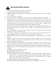
Warnings and Precautions 1. Read all of these warnings and save them for later reference. 2. Follow all warnings and instructions marked on this unit. 3. Unplug this unit from the wall outlet before cleaning. Do not use liquid or aerosol cleaners. Use a damp 4. Do not use this unit in or near water. 5. Do not place this unit on an unstable cart, stand, or table. The unit may fall, causing serious damage. 6. Slots and openings on the cabinet top, back, and bottom are provided for ventilation.
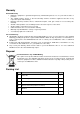
Warranty Standard Warranty • Datavideo equipment is guaranteed against any manufacturing defects for one year from the date of purchase. • The original purchase invoice or other documentary evidence should be supplied at the time of any request for repair under warranty. • Damage caused by accident, misuse, unauthorized repairs, sand, grit or water is not covered by this warranty. • All mail or transportation costs including insurance are at the expense of the owner.
Introduction Thank you for purchasing the Datavideo PTC-100 Full HD PTZ Camera. We hope you will be pleased with your purchase, and with what you can achieve with this camera. In order to get the most out of your camera, we recommend that you spend some time getting familiar with this manual, as it will describe all the functions of this unit. In addition, you’ll find some useful background information on how to install and set up this Pan, Tilt and Zoom camera.
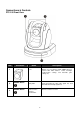
Connections & Controls PTC-100 Front View Item Illustration 3 Description Lens Built-in 1/3” Sony Exmor 3.0MP CMOS HD color camera with white balance control, backlight compensation settings, and automatic gain settings etc. Shown above Tally LED Tally lamp lights-up when tally signal has been transmitted to the tally signal box. Shown above Sensor for the Remote Commander Remote controller receiver.
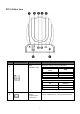
PTC-100 Rear View Item 1 Illustration Function Description SW2: IRID&DVIP Setup Bold letters indicates factory default value. Setup Switch Number IRID #1 #2 CAM 1 Off Off On Off CAM 2 Off On CAM 3 On On CAM 4 Setup Switch Number #3 Off On 2 RS422 Communication Control Input Function DVIP RS422 Set #3 of SW2 to ON to connect RS422 and RJ45.
Item Illustration Function Description 3 HD-SDI OUT Video signal output 800mV+-10% 75Ω BNC 4 CVBS OUT Video signal output CVBS 1. 0Vp-p 75Ω BNC 5 HDMI OUT Video signal output16-bit YCbCr 4:2:2 DVIP Communication Control Input Set #3 of SW2 to OFF to connect RJ45 and DVIP.
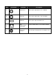
PTC-100 Bottom View Item 1 Illustration Shown above 2 3 Shown above Function Description Tripod screw hole SW1: DIP Switch setup PTZ cameras can be connected in series of up to 225 devices; each PTZ camera has its own ID number and may not be repeated. Screw Hole Ceiling bracket mounting screw holes. PTZ cameras can be connected in series 255; each PTZ camera machine must be set to the ID position.
SW1: ID Setup: PTZ cameras can be connected in series of up to 225 devices; each PTZ camera has its own ID number and may not be repeated.
DIP switch setting, as shown below: Set to 000, then the image display will show: ID 1.
PTC-100 Installation Guide Step 1 Set the IMAGE FLIP switch on the rear panel to ON. Step 2 Attach the retaining wire to the junction box in the ceiling. Use a screw hole and a screw (not supplied) in the junction box to attach the retaining wire. Step 3 Attach the ceiling bracket (B) to the junction box on the ceiling. Make sure to align the holes in the bracket with those in the junction box.
Step 4 Attach the ceiling bracket (A) to the bottom of the camera using the 3 screws. Align the screw holes on the bottom of the camera with those in the ceiling bracket to the camera. Tighten the screws a bit at a time in the numbered order shown in the illustration. Attach the retaining wire using the screw designated as number ○ 3 above. After all of the screws are inserted and temporarily tightened properly, securely tighten each one in turn.
Step 5 Insert the protrusions raised on the ceiling bracket (A) into the spaces prepared in the ceiling bracket (B), and temporarily attach them by pushing the ceiling bracket (A) to the rear. Step 6 While pushing up on the front part of the camera, attach it using the three screws provided, starting with the screw at position.
Step 7 Connect the cables to the connectors on the rear of the camera. Removing the camera Step 1 Remove the 3 screws used to attach the camera in step 6 of “Installation”. Step 2 While pushing the entire camera up towards the ceiling, move the camera to the front. The hooks will disengage, and you can remove the camera.
OSD Operational Description ◎ Selection marked as "*", represents factory default value Menu Tree Structure MAIN MENU MODE ITEM NOTES DZOOM ON/ OFF* DEFAULT Return to default setup RETURN Return to previous setup page DZOOM ON/ OFF* DEFAULT Return to default setup RETURN Return to previous setup page DZOOM ON/ OFF* TRIGGER Press to enable PUSH AUTO DEFAULT Return to default setup RETURN Return to previous setup page BRIGHTNESS -7> -6> -5 …> 0* > +1> …> +7 GAIN LIMIT +6db* > +8db
DAY/ NIGHT DEFAULT Return to default setup RETURN Return to previous setup page DEFAULT Return to default setup RETURN Return to previous setup page DEFAULT Return to default setup RETURN Return to previous setup page DEFAULT RETURN RED GAIN Return to default setup Return to previous setup page AE DAY* NIGHT WHITE BALANCE AUTO* BLUE GAIN DEFAULT RETURN TRIGGER PUSH AUTO DEFAULT RETURN NOISE REDUCTION MANUAL CAMERA SETUP 0> 1> 2> ...> 212*> 213> ...> 255 0> 1> 2> ...> 148*> 149> ...
1080/ 50i (PAL) 1080/ 29.97p (NTSC) 1080/ 25p (PAL) VIDEO SETUP 720/ 59.94p (NTSC) 720/ 50p (PAL) 720/ 29.97p (NTSC) 720/ 25p (PAL) OSD SETUP HORIZONTAL 0> 1> ...> 96*> 97> ...> 198> 199 VERTICAL 0> 1> ...> 36* > 37> ...> 98> 99 DEFAULT Return to default setup RETURN Return to previous setup page HORIZONTAL 0> 1> ...> 96*> 97> ...> 198> 199 VERTICAL 0> 1> ...> 36* > 37> ...> 98> 99 DEFAULT Return to default setup RETURN Return to previous setup page HORIZONTAL 0> 1> ...> 96*> 97> .
CAMERA SETUP > FOCUS SETUP Users can setup focus application. Factory settings as shown below: FOCUS MODE DZOOM TRIGGER DEFAULT RETURN Auto OFF OFF OFF MODE: This function is used for setting up focus mode, it can be set to Auto/ Manual/ Push Auto. 1. Auto: Select auto mode to enable automatic adjustment of the focus position. 2. Manual: Select manual mode to setup focus position manually. 3.
GAIN LIMIT: Setup Gain Limit, setup range = 0~28 (Default Setup: 6). SHUTTER: Shutter Speed consist of 5 types of mode: NTSC: 1/1,1/2,1/30,1/60,1/10000 and PAL: 1/1,1/2, 1/25,1/60,1/10000 (Default Setup: 1/30). IRIS: Setup Iris value, iris setup range = F14~F1.6 (Default Setup: F1.6). WDR: Setup Effio double scan WDR function ON/ OFF. BLC: System will auto detect its brightness and the backlight compensation is auto defined by the system. DEFAULT: Return to default setup.
CAMERA > WHITE BALANCE Users can setup white balance application. Factory settings as shown below: WHITE BALANCE MODE AUTO MANUAL PUSH AUTO DEFUALT RETURN AUTO OFF OFF OFF OFF MODE: Three types of WB mode setup: AUTO/ MANUAL/ PUSH AUTO (Default Setup: AUTO). AUTO: System auto adjusts the white balance condition and maintains it, no matter how the environment changes. MANUAL: Set white balance to manual mode to manually adjust red or blue gain (Setup Value: 0~255), higher the value darker the color.
CAMERA SETUP > EFFECT SETUP User can setup some image application and effect. Factory settings are as shown below: EFFECT SETUP NEGATIVE MIRROR FREEZE DEFAULT RETURN OFF OFF OFF OFF NEGATIVE: Negative effect can be set to ON/ OFF (Default Setup: OFF). MIRROR: Three Types of MIRROR mode: OFF/ HORIZONTAL/ ROTATE (Default Setup: OFF). FREEZE: Freeze function can be set to ON/ OFF (Default Setup: OFF). DEFAULT: Return to default setup. RETURN: Return to previous setup page.
SPEED (DPS): Setup the moving speed, higher the value faster the speed. DWELL TIME (SEC): Setup the dwell time after cruise function stops (Dwell Time Range: 1~127 Sec.). EXECUTE: Precede preset function. DEFAULT: Return to default setup. RETURN: Return to previous setup page. VIDEO SETP User can setup video application. Factory settings are as shown below: VIDEO SETUP MODE HORIZONTAL VERTICAL DEFAULT RETURN 1080/ 59.94i 96 36 OFF MODE: Eight types of video modes: NTSC: 1080/ 59.
OSD SETUP OSD SETUP ID DISPLAY TITLE DISPLAY TITLE EDIT ZOOM RATIO LANGUAGE DEFAULT RETURN OFF OFF TITLE OFF ENGLISH OFF ID DISPLAY: To reveal or hide ID, can be set to ON/ OFF. TITLE DISPLAY: To reveal or hide Title, can be set to ON/ OFF. TITLE EDIT: Enter a title name (maximum 15 characters). ZOOM RATIO: To reveal or hide ZOOM RATIO, can be set to ON/ OFF. LANGUAGE: Supports three types of languages: ENGLISH/ 繁中/ 簡中. DEFAULT: Return to default setup.
Remote Controller Button Description Menu Setup PTC-100 requires HDMI monitor to browse the current setup status, and operation setup using keyboard or remote controller buttons: MENU/ UP/ DOWN/ LEFT/ RIGHT/ A/FOCUS. Setup methods of all menu function items are similar. Press the MENU button to enter or exit camera menu options, press UP or DOWN arrow button to select the menu option. Use LEFT or RIGHT arrow button to enter sub-menu option or press A/ FOCUS button to exit sub-menu option.
Item 1 2 3 Illustration Function Description Color Bar Setup (MODE) Use the MODE button to setup and adjust the screen brightness and color density. PAN/ TILT Control (RESET) Press RESET button to face the camera back to the front. Camera Select (CAM1~CAM4) Operating more than one camera with the Remote Controller. 4 Position Setup (0~9) (PRESET) (SET) Set the IRID (SW2) switch (at the rear of the main unit) of the camera which you intend to operate: 1/ 2/ 3.
Item Illustration Function Description Auto Focus Control (A/ FOCUS) To focus the camera on a subject automatically Press the A/ FOCUS button. The camera focuses on the subject at the center of the screen automatically. 6 Exit Sub-Menu Option Press A/ FOCUS button to exit sub-menu option. 7 Brightness Control (A/ Gain) (GAIN+) (GAIN-) When shooting a subject within a dark environment Press GAIN+ button brighten-up or GAIN- to darken the environment.
Item Illustration Function Description 12 Enter/ Exit Camera Menu Option Enter or Exit Camera Menu Option 13 Zoom in/ Zoom Out Button Enlarge Image (TELE) Minimize Image (WIDE) Zooming Press either TELE button to zoom-in when the subject appears close to the camera or WIDE button to zoom-out when the subject appears far away from the camera. 14 Speed Button (FAST/ SLOW) Switching the Zoom In/ Out Speed Press this button to switch to diffent speed (High/ Low).
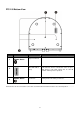
Dimension 31
Specification Item No. Description PTC-100 SD/ HD HD-SDI/HDMI + CVBS PTZ Camera Video Image Device 1/3” Sony Exmor 3.0MP CMOS sensor Picture Elements Approx. 3M (1920H × 1080V) Resolution SD / HD / FHD Signal system 480i (CBS) 576i (CBS) 720_50p/720_59.94p/ 720_25p/720_29.97p/ 1080_50i/1080_59.94i/ 1080_25p/1080_29.97p Min. Illumination Less than 3.0 lx (F1.6, 50 IRE) S/N Ratio More than 50 dB Electronic Shutter 1/1 to 1/10,000 s, 22 steps Gamma 0.
Motion Detection - MD Sensitivity - Alarm - Privacy Masking - White Balance Auto(ATW) / Manual / Push Auto Auto/Manual Gain Control (6 to 28 dB, 2 dB steps) Back Light Comp. On / Off Digital Zoom 12X Mirror Horizontal / Rotate Freeze On / Off Positive / Negative On / Off Color Bar On / Off (Full Bar) Power Sleep Design Yes Pan / Tilt / Zoom Mini.
Day / Night IR-Cut filter Removable Yes IR Distance - LED (pcs/angle) - Light Transistor - Wavelength - Lens Lens Type Mototized 20X Zoom Focal Length f=4.7 mm (W) to 94.0 mm (T) Aperture Range F1.6 to F3.5 Angle of View 54.1°(W-end) to 2.9°(T-end) Aspect ratio 16 : 9 Lens Control DC / Manual Others Weather Proof - Vandal Proof - Bracket Yes Sync.
Protocol Pelco D/ P; Sony VISCA Baud Rate 9600bps Video Output (HD) HD-SDI (BNC)/ HDMI Video Output (SD) BNC Video Format Output 1Vp-p/ 75Ohms. Audio - FAN - Heater - Tally LED Dimension (incl. BNC) 2 LED Built in the PTZ Zoom Module Side 218mm (H) x 173mm (W) x 185.5mm (D) Weight 2.
Service & Support It is our goal to make your products ownership a satisfying experience. Our supporting staff is available to assist you in setting up and operating your system. Please refer to our web site www.datavideo-tek.com for answers to common questions, support requests or contact your local office below. Datavideo Global Website: www.datavideo-tek.com Datavideo Corporation Tel: +1 562 696 2324 Fax: +1 562-698-6930 E-Mail: contactus@datavideo.