Rev.
Disclaimer Data Ltd., Inc. (DLI) reserves the right to make changes in specifications and other information contained in this document without prior notice, and the reader should in all cases consult DLI to determine whether any such changes have been made. The information in this publication does not represent a commitment on the part of DLI.
Table of Contents Thank You! ...................................................................................................................................... 4 DLI 7200 Peripherals and Accessories ........................................................................................... 4 Hardware Overview ......................................................................................................................... 5 Setting Up the DLI 7200 Terminal ........................................
Thank You! Data Ltd Inc. would like to thank you for selecting the DLI 7200. The DLI 7200 was designed as a forward thinking product that is modular in design and upgradeable.
Hardware Overview Front Panel Ambient Light Sensor Power Button Two Programmable Buttons Programmable Button LCD with Touch Screen Impact Resistant Case Microphone Programmable Keyboard DLI 7200 Product Manual 5 Rev.
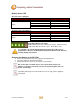
Front Panel Status Indicator LEDs The front panel includes three status indicator LEDs, Imager, Bluetooth and Power / Charge status. Bluetooth Imager Indicator LED Imager Bluetooth Status Solid Red Flash Green Description Imager On Good Read Blinking Blue No Light Enabled Disabled or Not Available Refer to Battery Status LED section.
Side Panels w/ Optional 2-in-1 Module Left Side Right Side Headphone Jack Programmable Button Two Programmable Buttons Mini USB DLI 7200 Product Manual 7 Rev.
Back Panel Part Number 7200A Part Number 7200B 2-in-1 RFID / NFC & MSR 2MP Camera w/ Flash Hot-swappable Battery Pack Hot-swappable Battery Pack (In Stand-by Mode ONLY) DLI 7200 Product Manual (In Stand-by Mode ONLY) 8 Rev.
Setting Up the DLI 7200 Terminal 1. 3. 4. 5. Unpack the carton and verify its contents. – See Below Charge the main battery for two hours. Power on the terminal via the power button on the top of the terminal. Let the device load and end on the Desktop screen.
Battery Status LED On Power Source (Charger) Battery Indicator Light Power Status Battery Solid Green Description Powered On Solid Green Blinking Green Blinking Yellow Blinking Red Capacity level = 100% Capacity level > 70% Capacity level > 20% - < 70% Capacity level < 20% Off Power Source (No Charger) Battery Indicator Light Power Battery Solid Green Status Description Powered On Solid Green Solid Yellow Solid Red Blinking Red Capacity level > 70% Capacity level < 70% - > 20% Capacity level <
Power Management Utility The DLI 7200 includes a comprehensive suite of power management functions. The power management is based upon the ACPI Standard (Advanced Configuration and Power Interface Specification) and is operated within the Embedded Controller (EC) at low level management. The Power Management Utility is accessible in the Control Panel.
Select Battery to expand the options (shown below). Select Low battery level and give the On battery a percentage. 50% is what is shown; this number can be changed to better fit the needed requirements. After selecting a low battery level, now select a Low battery action. Select Shut down for On Battery. Select Apply and OK. Once external power is removed (i.e.
Using the Stylus The stylus functions as a mouse; generally, a tap is the same as a mouse click. Tap: Double Tap: Drag: Right Mouse Click: Tap the touch screen once to open menu items and select options. Double tap is used to perform a variety of actions, such as opening a program, opening a folder, or selecting a word of text. Hold the stylus on the screen and drag across the screen to select text and images. Drag in a list to select multiple items.
3. Follow the instructions and the crosshairs to calibrate. 4. Finally select Apply and then OK. The calibration is complete. Do not write on the terminal display with ink pens or use other sharp objects that may damage the display. DLI 7200 Product Manual 14 Rev.
Using the Programmable Keys The DLI 7200 has 7 integrated function keys. Each key is user configurable via the DLI KeyMon Utility. The keys can be assigned to perform executable applications or Data Ltd. predefined functions. The predefined functions are as follows: Left Button – Barcode Scanner F1 – DLI On-Sceen Keyboard (OSK) F4 – GPS Demo Right Button – Camera Demo The DLI KeyMon utility can be launched from the system tray or from the Start>Programs>DLI>DLI KeyMon.
4. To assign an application choose External program and tap on the browser icon. Browser Icon 5. The user is returned to the assign menu once the selection has been chosen from the browser icon. Selecting the apply button saves the change to the key. The path to the application will appear in blue below the Current Assignment. DLI 7200 Product Manual 16 Rev.
6. To select a predefined action or keystroke choose Command and tap the down arrow to display a drop-down menu. The drop-down menu has a list of various actions and keystrokes to choose from. Once you have selected the command, tap the apply button to save. 7. To Close the DLI KeyMon select File and then Exit or tap on the “X” on the top right of the Main Window. This will close the KeyMon GUI but remain in the system tray. DLI 7200 Product Manual 17 Rev.
Using the WiFi Radio The DLI 7200 has a PCIe 802.11a/b/g/n integrated radio. In Windows 7 the radio is configured using the Windows Network and Sharing Center. With older versions of Windows the radio is configured by Intel PROSet. Please contact Technical Support (See page 40) if you have any questions configuring your radio. Windows provides the following features to Administrators and end-users: Connect or disconnect. View Available Networks and network mapping.
Selecting Open Network and Sharing Center will bring you to the window below. Here you can view your Network Map, your Active Networks, your Connection types and info. You can also set up new connections or networks. Enter a domain or workgroup and edit sharing options. Selecting Set Up a Connection or Network brings up an easy to use wizard that helps create a connection to your network and or the Internet. Choose the option that fits what you need to do. DLI 7200 Product Manual 19 Rev.
If the SSID is not broadcasted you will need to select ‘Manually connect to a wireless network.’ This option will allow to you create a profile to add the SSID, Security type, and Encryption type. Select Next to connect. DLI 7200 Product Manual 20 Rev.
Using the Bluetooth Radio The internal Bluetooth Class II wireless radio in the DLI 7200 is enabled by default. Microsoft™ Bluetooth software comes pre-installed on your terminal. Pairing an Accessory to the DLI 7200 The icon in the system tray offers shortcuts to the Bluetooth Settings window, the Bluetooth File Transfer Wizard and the Add New Connection Wizard. Press and hold the stylus on the Bluetooth icon to open the Bluetooth device menu.
Using the Bluetooth Application 1. Make sure that either the Bluetooth indicator light is flashing or that there is a checkmark beside Enable Internal Bluetooth Wireless Radio (both indicate that Bluetooth is running) 2. Using your stylus, Right mouse click the Bluetooth Devices icon in the system tray. 3. Tap Add a Device to launch the Bluetooth Add Bluetooth Device Wizard. 4. Place the Bluetooth device (headset, keyboard, printer, etc.) in discoverable mode.
6. Select the pairing option that best works for you Bluetooth device. This option will vary per device. You have a limited time after selecting Enter the device’s pairing code to input the code. Select Next. If a pairing code is required, please read documentation that came with your Bluetooth device or contact the manufacturer. DLI 7200 Product Manual 23 Rev.
7. When the device has been successfully paired and added, the wizard is complete and the device is ready to use. Select Close to finish. DLI 7200 Product Manual 24 Rev.
Using the Barcode Scanner The DLI 7200 is available with an integrated barcode scanner located at the top of the unit. Newland® Class 2 Standard Range Imager To Decode a Barcode 1. Point the top of the DLI 7200 terminal directly at the barcode. The Imager faces straight toward of the top panel. The aimer should be oriented in line with the barcode to achieve optimal decoding. (Distance from barcode depends on size and quality of the barcode. Average range is 2 to 15 inches) 2.
3-in-1 Demo Software The DLI 7200 has an optional 2-in-1 Module and by default comes with a 3-in-1 Demo App on the Desktop. This demo will allow you to test and demonstrate proof of concept of the module. Desktop Icon 3-in-1 Demo 3-in1 Demo GUI 3 (Continued on next page) DLI 7200 Product Manual 26 Rev.
Barcode Scanner Select Scanner in the drop down menu. Then select EM3000. Tap Open, Claim and Enable in that order. Status should display successfully for all three. You can now scan barcode and display the data in the ScanData field. 3 To close the Scanner, select Disable, Release and Close in that order. Status should display successfully for all three. (Continued on next page) DLI 7200 Product Manual 27 Rev.
MSR Select MSR in the drop down menu. Then select IDTECH_MMII_RS232_1. Tap Open, Claim and Enable in that order. Status should display successfully for all three. You can now swipe your test card and display the data in the track fields. 3 To close the MSR, select Disable, Release and Close in that order. Status should display successfully for all three. (Continued on next page) DLI 7200 Product Manual 28 Rev.
RFID Select MSR in the drop down menu. Then select USSEN_USN3170_RS232_1. Tap Open, Claim and Enable in that order. Status should display successfully for all three. You can now wave your test RFID card and display the data in the track fields. 3 To close the RFID, select Disable, Release and Close in that order. Status should display successfully for all three. If you have any questions please contact DLI Support support@dataltd.com or 800.526.1299 ext. 774 DLI 7200 Product Manual 29 Rev.
SAM Card Installation Part of the DLI 2-in-1 Module is an RFID Reader that requires a SAM Card to function correctly. The SAM Card slot is found on the back of the 2-in-1 Module and has special instructions for installation. Warning! Do not install/remove module while unit is powered on or plugged in to AC. ATTENTION! When removing the 2-in-1 module, please be aware of exposed components. Use non-conductive tools. Do not remove module near any liquids or debris. 1.
SIM Card Insertion The SIM Card Slot is located in the battery bed on the back panel of the unit. To insert SIM Card follow the instructions on the SIM slot. Insert the SIM card with the card contacts facing toward the circuit board. The SIM Card Slot is intended for use of GPRS Wireless Radio ONLY. If you are unaware of what type of WWAN Radio you have please contact DLI Technical Support; (800) 526-1299 x774 or support@dataltd.com. The unit must be powered down prior to inserting the SIM card.
Using the GPS The optional GPS module with active antenna provides the SiRFstar III chip set and TTFF (Time to First Fix) technology which speeds the time to lock to a satellite. The Geohelix active antenna provides 25db gain. Along with each of these features Data Ltd’s patent pending RF antenna switching technology provides you with the functionality of switching between external and internal antennas without software requirements.
3. Once connected you can verify the Signal Quality, Satellite Location, Latitude, Longitude and Altitude. You can also view the Streaming NMEA data. You must be outside a building as GPS antennas do not work inside buildings. The green bars indicate a lock to a satellite. DLI 7200 Product Manual 33 Rev.
DLI 7200 Desktop Cradle Overview The DLI 7200 Cradle is a Desktop and Vehicle Cradle all in one. It features quick release and lock, flexible mounting, and power options for all types of applications and devices. When the DLI 7200 is seated in the Cradle, the Main Battery is charged in 2 hours. The patent pending RF design provides easier operation using internal and external antennas.
Front Panel Docked Spare Battery Ethernet Solid green Docked LED indicates connection established with Terminal. Back Panel The I/O ports and power supply connector are located on the back of the unit. Power Supply Connector The connector is to be used with the DLI series of power supplies. Please see below for a reference of recommended power sources. The Cradle can be powered by an external DC power source of 18VDC~22VDC.
Ethernet Communication Port The Ethernet connection supports 10/100mbps communication via a wired LAN. Standard Ethernet cables can be used to attach the cradle to a host system. VGA Port The VGA Connector is for an external display to transfer or mirror what is being displayed on the DLI Device. Connector Locations VGA Port Ethernet Power Right Panel K-Lock DLI 7200 Product Manual Two USB Ports 36 Rev.
Technical Assistance If you need assistance installing or troubleshooting, please contact your distributor or the Data Ltd. Inc. Technical Support Office. North America/Canada: Telephone: (800) 526-1299 ext. 774 (8 AM to 4 PM EST) E- mail: support@dataltd.com Website: http://dataltd.com/support-ticket Product Service and Repair Data Ltd. Inc. provides service for all its products through service centers throughout North America. To obtain warranty or non-warranty service, return the unit to Data Ltd. Inc.
Shipping your DLI Device Proper way to pack your DLI device DO NOT ship any DLI Device without a proper UPS or FedEx container. The DLI Container is not meant for stand-alone shipping. Place device in foam cover as shown. Place the wrapped DLI device in the correct position in the spacer inside the DLI Container. DLI 7200 Product Manual 38 Rev.
Using a proper UPS or FedEx container, line the bottom with Bubble Wrap, Air Pillows, Packing Foam, etc. Place the closed DLI container inside the lined Shipping Container. Seal the Shipping Container and ship to: DLI 5570 Lee Street, Suite 12 Lehigh Acres, FL. 33971 The dimensions of the box shown are 27x17x10. Fill the rest of the Shipping Container with packing material. DLI 7200 Product Manual 39 Rev.
Limited Warranty Data Ltd. Inc. warrants its products to be free from defects in materials and workmanship and to conform to Data Ltd. Inc. published specifications applicable to the products purchased at the time of shipment.
Data Ltd. Inc., Inc. extends these warranties only to the first end users of the products. These warranties are non-transferable. The limited duration of the warranty for the DLI 7200 is as follows: DLI 7200 terminal with the integrated modules are covered by a one-year limited warranty. Touch screens are covered by a one-year limited warranty. The limited duration of the warranty for batteries is one year. Use of any battery not sold/ manufactured by Data Ltd. Inc.
The compliance labels are located on the back of the unit: DLI 7200 FCC ID: CB10202064 DLI 7200 WPAN (Bluetooth) FCC ID: PIWBLUESLIM2 Model: BSLIM2(V) DLI 7200 GSM/GPRS FCC ID: NCMOMO6692 IC: 2734A-MO6692 Model: GTM669W DLI 7200 802.
FCC Compliance This device complies with Part 15 of the FCC Rules. Operation is subject to the following two conditions: (1) this device may not cause harmful interference, and (2) this device must accept any interference received, including interference that may cause undesired operation. This equipment has been tested and found to comply with the limits for a Class B digital device pursuant to Part 15 of the FCC Rules.
Canadian Compliance This Class B digital apparatus complies with Canadian ICES-003. Operation is subject to the following two conditions: (1) this device may not cause harmful interference, and (2) this device must accept any interference received, including interference that may cause undesired operation. To prevent radio interference to the licensed service, this device is intended to be operated indoors and away from windows to provide maximum shielding.
DLI 7200 Product Manual 45 Rev.