
Installation manual


Maxsys and MX Series Software Administrator’s Guide 259
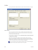
Background Image
The background image gives a visual representation of preprinted artwork, it is
not laser engraved. Click the ellipses (...) button to select the background image.
This image is display only and not produced.
Alpha Channel
Some products have areas that contain special features, e.g. a kinegram.
Depending on the material, these areas may be more sensitive to laser energy
causing bubbling or delamination of product layers. To prevent this from
occurring the laser power must be reduced in these areas.
A grayscale image can be created that represents the laser-receptive area of the
product and is used to control the laser power of selected elements on an area
basis. In this image, white corresponds to full laser power and black corresponds
to zero laser power. Gray levels are used to vary laser power between these two
extremes. This is done by an alpha blending process and the image mentioned
above represents the alpha channel.
The image must be of the same size as your layout and is cur
rently limited to a
fixed resolution of 96 dpi (which is enough for this purpose). For ID-1 layouts, the
alpha image should be 324 x 204 pixels and for ID-3 layouts, the alpha image
should be 472 x 332 pixels. The image is aligned to the bottom-left edge (0.0 / 0.0
Coordinate) of the layout.
This power reduction only works with bitmap based laser elements, not
with vectors.
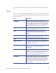
• Click the ellipses (...) to select an image to use for the alpha channel.
• To use this feature, an element’s Alpha Blending check box must be selected.
See Bitmap Settings tab of Element Properties.
• Select the emb ch
eckbox to embed the image in the layout. Once loaded, the
image is stored in the layout file. This is useful if the image might not be
persistent at the specified file path. If not embedded, ConCAD attempts to
load the image from the specified location every time the layout is opened. If
the file is no longer in the location, there will be an error when opening the
layout.
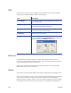
Guidelines
Guidelines that can be displayed on the front/back side are defined in the
respective lists by selecting Add Guideline, Edit Guideline, or Remove
Guidelines. The guidelines can be shown or hidden by using the View menu.
Units are in millimeters unless otherwise indicated.