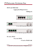
Datacom Systems Inc SPAN and Multi-link Aggregators/Regenerators USERguide SS series SPAN Aggregators/Regenerators VS series SPAN Aggregators/Regenerators VS series Multi-link Aggregators/Regenerators SS series SPAN VS series SPAN VS series Multi-Link June 2007 541-0106-U-A.01 © 2004-2007 by Datacom Systems Inc. All Rights Reserved.
Datacom Systems Inc Copyright Copyright © 2004-2006 by Datacom Systems, Inc. All rights reserved. Printed in the United States of America. No part of this publication may be reproduced, stored in a retrieval system, or transmitted, in any form or by any means, electronic, mechanical, photocopying, recording, or otherwise, without the prior written permission of Datacom Systems, Inc.
Datacom Systems Inc Compliance Testing CAUTION: Changes or modifications to this unit not expressly approved by the party responsible for compliance could void the user’s authority to operate the equipment. Certifications This equipment has been tested and found to meet the radiated and conducted emission limits for a Class A product of EN 55022 to the EMC Directive 89/336/EEC requirements.
Datacom Systems Inc 5 Contents What Shipped? . . . . . . . . . . . . . . . . . . . . . . . . . . . . . . . . . . . . . . . . . . . . . . . . . . . 6 Introduction . . . . . . . . . . . . . . . . . . . . . . . . . . . . . . . . . . . . . . . . . . . . . . . . . . . . . . 7 Attributes & Advantages . . . . . . . . . . . . . . . . . . . . . . . . . . . . . . . . . . . . . . . . . . . . 8 SINGLEstream™ SPAN SS-200 Series Aggregators/Regenerators Overview . . . . . 8 SS-200 Features & Benefits . . . . . . . . .
Datacom Systems Inc What Shipped ? SS series SPAN Aggregators/Regenerators 1 — SS-(200, 201, 202 or 203) 2 — Switching AC Adapters 2 — AC Power Cords 1 — Warranty Card 1 — QUICKinstall Guide 1 — USERguide VS series SPAN Aggregators/Regenerators 1 — VS-(1022BT-BT, 1062BT, 1031BT, 1031BT-02, 1082, 1082LX-BT, 1082SX-BT, 1082SX-SX, 1041SX-SX or 1022SX-SX) 2 — Switching AC Adapters 2 — AC Power Cords 1 — Warranty Card 1 — QUICKinstall Guide 1 — USERguide VS series Multi-link Aggregators/Regenerators 1 — VS
Datacom Systems Inc 7 Introduction The SPAN and Multi-link Aggregator/Regenerators can combine data from multiple Ethernet network segments into one stream of data. A single device, such as an intrusion detection system, protocol analyzer, or network probe can receive the aggregated data with just one network interface card (NIC). The SPAN and Multi-link Aggregator/Regenerators also have additional monitor ports, so multiple devices can receive the same data stream.
Datacom Systems Inc Attributes & Advantages • Connect any device (protocol analyzers, probes, intrusion detection system, more) for permanent simultaneous monitoring of multiple full-duplex links — eliminates the need for network connectors to be disconnected and connected each time a segment needs to be monitored. • Multipoint analysis enables you to seamlessly analyze a packet at multiple points in your network with one tool - know exactly what is happening to data as it moves through your network.
Datacom Systems Inc 9 The SINGLE stream™ series SPAN Aggregator/Regenerator faultlessly combines the two data streams, allowing any connected monitoring device to receive a full-duplex stream of data with one NIC. Additionally, the SINGLE stream™ series SPAN Aggregator/Regenerator provides a unique feature to help manage network resources - a second monitor port.
Datacom Systems Inc SS-200 Specifications PORT SPEED SINGLEstream™ NETWORKMb SS-200 SS-201 SS-202 SS-203 2(10/100BT) 2(100BT) 2(10/100BT) 2(100BT) MONITOR PORT SPEED Mb 2(10/100BT) 2(100BT) 2(10/100BT) 2(100BT) Feature TCP Reset NO NO YES YES Optional Rack Mount RMC-3 RMC-3 RMC-3 RMC-3 Specification Channel Cable Type Port Connectivity: NETWORK A NETWORK B TAP 1 A/B TAP 2 A/B Two SPAN CAT 5E RJ45 RJ45 RJ45 RJ45 Distance Limit 100 meter maximum length between network end-points.
Datacom Systems Inc 11 SS-200 Hardware Description — Figure 1 illustrates the SS-200 series SPAN Aggregator/Regenerator front panel. This is the location for all cable connections and status LEDs. Figure 1 - SS-200 Front Panel and functional diagram An explanation of each front panel legend follows: NETWORK A, B: These ports are RJ45 connectors used for network SPAN connection.
Datacom Systems Inc SS-200 Application & Hardware Installation — The SS-200 is used primarily in conjuction with two SS-100s to monitor and anlaysis Primary and Redundant Distribution Networks. Figure 2 depicts a typical set of monitoring tools attached to a primary circuit that automatically switch to the redundant circuit allowing uninterrupted monitoring using only one network interface card (NIC) for each monitoring device to see the combined traffic.
Datacom Systems Inc 13 Step 3. Connect the other primary network cables to the primary SINGLEstream™ S-100 RJ45 port NETWORK B connector. The NETWORK-B LINK LED illuminates indicating link has been established between the NETWORK B connector and primary NETWORK B device. !!!: The network is bidirectional Tx/Rx path sensitive and correct connection is indicated by simultaneously illuminated NETWORK-A and NETWORK-B “LINK” LEDs.
Datacom Systems Inc VERSAstream™ SPAN Series Overview — The VERSAstream™ SPAN aggregator/regenerator provides a single turnkey solution for 24x7 monitoring of redundant, failover, two-link EtherChannel and asymmetric network segments. It provides the ability to monitor one or two SPAN ports simultaneously, aggregating the data, and sending a single copy to two, three, four, six or eight connected network devices.
Datacom Systems Inc 15 VERSAstream™ SPAN Series Features & Benefits • Connect any compatible device (protocol analyzer, probe, intrusion detection system, more) for simultaneous monitoring of two full-duplex SPAN Ports - eliminates the need for network connectors to be disconnected and connected each time a segment needs to be monitored • Two, three, four, six or eight monitor ports allow multiple network devices to simultaneously monitor the same SPAN Ports, providing extended security and analysis optio
Datacom Systems Inc VERSAstream™ SPAN Series Specifications PORT SPEED VERSAstream™ NETWORKMb VS-1022BT-BT VS-1022SX-SX VS-1031BT VS-1031BT-02 VS-1041SX-SX VS-1062BT VS-1082 VS-1082LX-BT VS-1082SX-BT VS-1082SX-SX 2(10/100/1000) 2(1000SX) LC 1(10/100/1000) 1(10/100/1000) 1(1000SX) LC 2(10/100/1000) 2(10/100/1000) 2(1000LX) LC 2(1000SX) LC 2(1000SX) LC MONITOR PORT SPEED Optional TCP Reset Mb Rack Mount RMC-2 2(10/100/1000) NO RMC-2 2(1000SX) LC NO RMC-2 3(10/100/1000) NO RMC-2 3(10/100/1000) YES RMC-2
Datacom Systems Inc 17 VERSAstream™ SPAN Hardware Description — Figure 3 through Figure 12 illustrates the VERSAstream™ SPAN Series aggregator/regenerator front panel. This is the location for all cable connections and status LEDs.
Datacom Systems Inc Figure 6 - VS-1041LX-LX Front Panel and functional diagram Figure 7- VS-1041SX-SX Front Panel and functional diagram Figure 8 - VS-1062BT Front Panel and functional diagram SPAN and Multi-Link Aggregators/Regenerators • USERguide
Datacom Systems Inc 19 Figure 9 - VS-1082 Front Panel and functional diagram Figure 10 - VS-1082LX-BT Front Panel and functional diagram Figure 11 - VS-1082SX-BT Front Panel and functional diagram SPAN and Multi-Link Aggregators/Regenerators • USERguide
Datacom Systems Inc Figure 12 - VS-1082SX-SX Front Panel and functional diagram An explanation of each front panel legend follows: POWER: Two power supplies are provided for each module. Use of the second power supply is strongly recommended to assure uninterrupted monitoring. Furthermore, connecting the second power supply to a different external power source circuit than the first power supply eliminates power as a single point of failure.
Datacom Systems Inc 21 MONITOR: These ports are either RJ45 or duplex-LC connectors used for connection to NIC MONITOR card connectors of each network monitoring tool. network connections. The LED Display Code Table deciphers the RJ45 jacks with integrated LEDs that display line status and line speed of each port. The LED associated with each duplex-LC jack indicates when light signal has been detected on the respective Rx MONITOR port.
Datacom Systems Inc 2. Connect network cables to the VERSAstream™ NETWORK duplex-LC ports. The LED associated with each duplex-LC jack is solid green indicating when light signal has been detected on the respective Rx NETWORK port. 3. Connect analysis devices to the VERSAstream™ MONITOR ports. Two DRL494–2m cables are provided to connect analysis SC ports to the MONITOR duplex-LC ports.
Datacom Systems Inc 23 connecting the second power supply to a different external power source circuit than the first power supply eliminates power as a single point of failure. The POWER 1 and 2 LEDs illuminate indicating power 1 and 2, respectively, are on. Either LED not illuminated indicates a defective power source and immediate replacement is required to insure redundant power integrity. 2. Connect one network device duplex-SC plug to the FIBERtap™ duplex-SC B OUT and A IN connector. 3.
Datacom Systems Inc To connect the VERSAstream™ VS-1022BT-BT SPAN Series aggregator/regenerator, refer to Figure 15 and follow these steps: 1. Two power supplies are provided. Use of the second power supply is strongly recommended to assure uninterrupted monitoring. Connect both power supply barrel connectors into the power 1 and 2 ports, respectively, of the VERSAstream™.
Datacom Systems Inc 25 VERSAstream™ Multi-link Series Overview — The VERSAstream™ Multi-Link Aggregator can combine data from multiple Ethernet network segments into one stream of data. A single Gigabit device, such as an intrusion detection system, protocol analyzer, or network probe can receive the aggregated data with just one network interface card (NIC). The VERSAstream™ also has an additional monitor port (2 and 4-port models available), so multiple Gigabit devices can receive the same data stream.
Datacom Systems Inc Features and Benefits • Connect any Gigabit (Gbps) device (protocol analyzers, probes, intrusion detection system, more) for permanent simultaneous monitoring of multiple full-duplex links — eliminates the need for network connectors to be disconnected and connected each time a segment needs to be monitored.
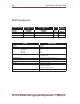
Datacom Systems Inc 27 VERSAstream™ Multi-link Series Specifications NETWORK PORT SPEED Mb 6(10/100/1000) 8(10/100/1000) 8(1000SX) LC 6(10/100/1000) 6(1000SX) LC 12(10/100/1000) 10(10/100/1000) VERSAstream™ VS-1026BT-BT VS-1028 VS-1028SX VS-1046 VS-1046SX VS-1412 kit VS-1610 kit MONITOR PORT SPEED Mb 2(10/100/1000) 2(1000SX) LC 2(1000SX) LC 2(1000SX) LC & 2(10/100/1000) 4(1000SX) LC 4(1000SX) LC 4(1000SX) LC & 2(10/100/1000) Feature Channel — Network: Optional Rack Mount RMC-2 RMC-2 RMC-2 RMC-2 RMC-2
Datacom Systems Inc VERSAstream™ Multi-link Hardware Description — Figure 16 through Figure 22 illustrates the VERSAstream™ Multi-link Series aggregator/regenerator front panel. This is the location for all cable connections and status LEDs.
Datacom Systems Inc 29 Figure 19 - VS-1046 Front Panel and functional diagram Figure 20 - VS-1046SX Front Panel and functional diagram Figure 21 - VS-1412 Front Panel (1 of 2 in kit) and functional diagram SPAN and Multi-Link Aggregators/Regenerators • USERguide
Datacom Systems Inc Figure 22 - VS-1610 Front Panel (1 of 2 in kit) and functional diagram An explanation of each front panel legend follows: POWER 1, 2: Two power supplies are provided for each module. Use of the second power supply is strongly recommended to assure uninterrupted monitoring. Furthermore, connecting the second power supply to a different external power source circuit than the first power supply eliminates power as a single point of failure.
Datacom Systems Inc 31 DAISY: DAISY ports IN and OUT are RJ45 connectors cabled to the next aggregator. The LED Display Code Table deciphers the RJ45 jacks with integrated LEDs that display line status and line speed of each port. Analyzing/Monitoring Gigabit EtherChannel CONCERN: The popularity of web-based services has increased bandwidth consumption. An increase in bandwidth consumption has also brought increased network problems.
Datacom Systems Inc Unlike other solutions, the VERSAstream™ Multi-Link Aggregator when deployed with SINGLEstream™ Gigabit Aggregation Taps or other Datacom Systems Gigabit Ethernet taps provides complete visibility into Gigabit EtherChannel, while allowing network professionals to use their existing analysis and monitoring devices. The VERSAstream™ Multi-Link Aggregator is a simple "plug and play" solution that can combine data from multiple Gigabit Ethernet network segments into one stream of data.
Datacom Systems Inc 33 To connect the VERSAstream™ VS-1028 Multi-link Series aggregator/regenerator, refer to Figure 23 and follow these steps: 1. Two power supplies are provided. Use of the second power supply is strongly recommended to assure uninterrupted monitoring. Connect both power supply barrel connectors into the power 1 and 2 ports, respectively, of the VERSAstream™.
Datacom Systems Inc VS-1028 with Taps Application — shown in Figure 24, focuses on a typical VERSAstream™ VS-1028 Multi-Link Aggregator application deployed with Datacom Taps to combine traffic from different network segments and output the aggregated data to either a single network tool or two connected monitoring devices.
Datacom Systems Inc 35 To connect the VERSAstream™ VS-1028 Multi-link Series aggregator/regenerator, refer to Figure 24 and follow these steps: 1. Two power supplies are provided. Use of the second power supply is strongly recommended to assure uninterrupted monitoring. Connect both power supply barrel connectors into the power 1 and 2 ports, respectively, of the VERSAstream™.
Datacom Systems Inc VS-1028 SPAN and In-line Application — shown in Figure 25, focuses on a typical VERSAstream™ VS-1028 Multi-Link Aggregator deployed to gain complete visibility into your SPAN and In-Line environments combining traffic from up to 8 different segments and outputting the aggregated data to two connected monitoring devices. Monitoring or analyze with multi-segment aggregation means less deployment and maintenance costs.
Datacom Systems Inc 37 To connect the VERSAstream™ VS-1028 Multi-link Series aggregator/regenerator, refer to Figure 25 and follow these steps: 1. Two power supplies are provided. Use of the second power supply is strongly recommended to assure uninterrupted monitoring. Connect both power supply barrel connectors into the power 1 and 2 ports, respectively, of the VERSAstream™.
Datacom Systems Inc VS-1610 kit Application — shown in Figure 26, focuses on a typical VERSAstream™ VS1610 kit (Two VS-1610s mounted in RMC-2 Rack Mount Chassis and daisy-chained together) Multi-Link Aggregator deployed.
Datacom Systems Inc 39 To connect the VERSAstream™ VS1610 kit Multi-link Series aggregator/regenerator, refer to Figure 26 and follow these steps: 1. Two power supplies are provided. Use of the second power supply is strongly recommended to assure uninterrupted monitoring. Connect both power supply barrel connectors into the power 1 and 2 ports, respectively, of the VERSAstream™.
Datacom Systems Inc SPAN and Multi-Link Aggregators/Regenerators • USERguide
Datacom Systems Inc 41 Customer Service This USERguide was written to help you get to know your new SINGLEstream™ Link Aggregation Taps quickly and easily. We would welcome any comments or suggestions you may have regarding this USERguide. Please send your remarks and recommendations via mail, telephone, facsimile, or Internet E-mail. Datacom Customer Service personnel are available from 8:30 AM to 5:30 PM Eastern time, weekdays. Customer Service is available via telephone, facsimile, and Internet E-mail.
Datacom Systems Inc SPAN and Multi-Link Aggregators/Regenerators • USERguide
Datacom Systems Inc www.datacomsystems.com © 2004 by Datacom Systems Inc. All Rights Reserved.