
- SPAN and Multi-link Aggregators/Regenerators USER Guide


Datacom Systems Inc
SPAN and Multi-Link Aggregators/Regenerators • USERguide
11
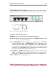
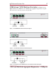
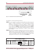
SS-200 Hardware Description — Figure 1 illustrates the SS-200
series SPAN
Aggregator/Regenerator
front panel. This is the location for all cable connections and status LEDs.
Figure 1 - SS-200 Front Panel and functional diagram
An explanation of each front panel legend follows:
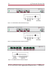
NETWORK A, B: These ports are RJ45 connectors used for network SPAN connection.
TAP 1 A/B and 2 A/B: These RJ45 connector ports are cabled to the NIC MONITOR card Port RJ45 connec-
tors of each network monitoring tool.
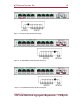
LINK: The NETWORK-A LINK LED illuminates indicating link has been established between the NETWORK A
connector and NETWORK A device. The NETWORK-B LINK LED illuminates indicating link has been
established between the NETWORK B connector and NETWORK B device. The TAP 1 LINK LED illumi-
nates indicating link has been established between the TAP 1 connector and monitoring device NIC (net-
work interface card.) The TAP 2 LINK LED illuminates indicating link has been established between the
TAP 2 connector and monitoring device NIC (network interface card.)
ACT: The NETWORK A and NETWORK B ACT LEDs illuminate as data is passed back and forth between the
NETWORK A and NETWORK B devices. The TAP 1 ACT LED illuminates as data is passed to the TAP 1
monitoring device. The TAP 2 ACT LED illuminates as data is passed to the TAP 2 monitoring device.
POWER: The POWER LED illuminates indicating power is on.