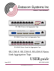
Datacom Systems Inc Access Your Network TM SS-1200-S Series Link Aggregation Taps SS-2200-S Series Dual-Link Aggregation Taps SS-4200-S Series Quad-Link Aggregation Taps SS-1200-S, SS-2200-S, SS-4200-S Series Link Aggregation Taps USER guide June 2012 541-0132-U-B.
Product Description Datacom Systems Inc. SINGLEstream™ SS-1200-S Series Link Aggregating Taps, the SS-2200-S Series Dual-Link Aggregating Taps and the SS-4200-S Series Quad-Link Aggregating Taps are made to be adaptable. The hard-wired TAP ports serve only as In-Line taps and the remaining Any-to-Any ports can be configured by the Command Line Interface (CLI) to be either input or output ports.
SS-1200-S, SS-2200-S and SS-4200-S Series Link Aggregating Taps © 2012 Datacom Systems Inc All rights reserved. No parts of this work may be reproduced in any form or by any means - graphic, electronic, or mechanical, including photocopying, recording, taping, or information storage and retrieval systems - without the written permission of the publisher. Products that are referred to in this document may be either trademarks and/or registered trademarks of the respective owners.
Contents 5 Table of Contents Section 1 Terms of Use 9 1 Copyright ................................................................................................................................... 9 2 License................................................................................................................................... Agreement 9 3 Trademark ...................................................................................................................................
SS-1200-S, SS-2200-S and SS-4200-S Series Link Aggregating Taps ......................................................................................................................................................... 27 SHOW GROUPS (SH GR) SHOW MANAGEMENT ......................................................................................................................................................... (SH MA) 27 SHOW PORT ............................................................................
Contents Section 5 Hardware Installation 7 61 1 TAP Connection ................................................................................................................................... 61 Copper SS-1200BT-S .......................................................................................................................................................... and SS-2200BT-S series 61 Fiber Optic SS-1200LX-S ......................................................................................
Terms of Use 1 9 Terms of Use The following terms and conditions relate to the use of this document. Please note that Datacom Systems Inc. reserves the right, at its entire discretion, to change, modify, add, or remove portions of these Terms of Use at any time. Please read the Terms of Use carefully as your use of this document is subject to the Terms of Use stipulated herein. 1.1 Copyright Copyright© 2011 by Datacom Systems, Inc. All rights reserved. Printed in the United States of America.
1.5 SS-1200-S, SS-2200-S and SS-4200-S Series Link Aggregating Taps Certifications and Marks CAUTION: Changes or modifications to this unit not expressly approved by the party responsible for compliance could void the user’s authority to operate the equipment.
Overview 2 11 Overview The SINGLEstream family of products increases network visibility and leverages your investment in network analyzers, probes, and security equipment by allowing you to simultaneously monitor as many supported configurable ports as you may need to fit your peripheral network tools. Greater visibility accelerates problem resolution, reduces downtime and increases enterprise productivity.
2.
Overview 13 Installed Management RJ45 port and Serial DB9 port allow for complete configuration through a simple, easy to use Command Line Interface (CLI). Datacom Customer Service Support is available via: Phone: +1 315 463-9541 Website: www.datacomsystems.com 2.5 SINGLEstream™ Series Common Specifications Management Port (front): RJ45 @ 100 Mbps Full-Duplex The factory configured IP Address, Subnet Mask and Default Gateway are as follows: IP Address: 192.168.1.1 Subnet Mask: 255.255.0.
2.
Overview 2.8 15 SS-4200 Series Model Specific Specifications SS-4210BT-SFP-S: Tap Connections: 4 - 10/100/1000BaseT In-Line (RJ45 Connectors) Any-to-Any Ports: 2 - SFP* *SFP = Small Form Pluggable can be LX, SX or 1000Mbs copper (Support Datacom supplied only) IMPORTANT: All BT taps can be configured to have traffic, for example TCP resets, injected from Any-to-Any ports.
Hardware 3 17 Hardware Front panel images of the SS-1200-S, the SS-2200-S and the SS-4200-S series are provided in this section. 3.
3.2 SS-1200-S, SS-2200-S and SS-4200-S Series Link Aggregating Taps SS-2200 Series Front Panels SS-2206BT-BT-S SS-2206SX-SFP-S SS-2210BT-BT/SFP-S 3.
Hardware 3.4 19 Front Panel Description This section provides a illustration and description of the front panel of the SS-1200-S, SS-2200-S and SS-4200-S series. An explanation of each front panel legend follows: 3.4.1 Power Two switching AC adapter power supplies are provided for each configurable unit. Although only one power supply is required to power the module, use of a second independent power source is strongly recommended to assure uninterrupted monitoring.
SS-1200-S, SS-2200-S and SS-4200-S Series Link Aggregating Taps LX-BT/SX-BT - TAP (SS-1204LX-BT-S and SX-BT-S port 3 and port 4) are dual-duplex LC connectors for connection to network segments. The LEDs to the right of the dual-duplex LC connectors are solid green when a light level link has been detected by the respective TAP Rx port.
Hardware 21 LX-BT/SX-BT - The LEDs located to the right of the SFP connectors are solid green indicating a link has been detected between the respective Any-to-Any Rx port and network device/tool Tx port or network segment. The LEDs are flashing green when data is passed. LX-SFP/SX-SFP - The LED located below and slightly left of center of the SFP connectors are solid green indicating a link has been detected between the respective Any-to-Any Rx port and network device/tool Tx port or network segment.
3.5.1 SS-1200-S, SS-2200-S and SS-4200-S Series Link Aggregating Taps Serial DB9 The SERIAL connector port is a shielded DB9 Female and is cabled to the COM port of any compatible network tool or PC where terminal emulation software resides. The cable is a parallel straight-through cable (EIA232 Standard, DRL512-2M-R serial cable, DB9 M/F straight thru) with no cross-overs or self-connects in the connector hoods.
Initial Configuration 4 23 Initial Configuration IMPORTANT: Prior to initial configuration of the hardware, it is imperative to review the entire Initial Configuration section before proceeding to the Installation section. NOTE: HyperTerminal is the preferred terminal emulation program and Microsoft© DOS-Windows Telenet is the preferred Telnet client.
SS-1200-S, SS-2200-S and SS-4200-S Series Link Aggregating Taps Base Prompt: This is the text presented to the user logging in to use the CLI (default values shown). All Usernames and passwords are case-sensitive. Enter Username: Administrator Enter Password: admin > Superuser log in: Example: > SU Enter Password: password # 4.1.2 Password Recovery Password Recovery is provided for a user that has forgotten the Superuser and/or Administrator login password.
Initial Configuration Example: > ? Available commands: ADD USER DELETE USER EDIT USER EXIT HELP POWER STATUS SET DATE SET GATEWAY SET IP SET LINK PROTECT SET PING SET PORT GROUP SET PORT MONITOR SET PORT NAME SET PORT SPEED SET PORT VTAG SET PORT VTAP SET PROMPT SET SNMPv3 SET SNMPv3 SUPERUSER SET SSH SET SSH KEY SET SUBNET SET TCP PORT SET TELNET SET TIME SET UPGRADE SHOW SHOW GROUPS SHOW MANAGEMENT SHOW PORT CONFIG SHOW PORT ROUTING SHOW PRODUCT SHOW TIME SHOW USERS SU SU SET PASSWORD 4.1.3.
4.1.3.
Initial Configuration 4.1.3.5 27 SHOW GROUPS (SH GR) This command displays all ports as designated by the administrator (Superuser) as belonging to the same logical group. Specifically, groups can be configured as if they were a single logical port, enabling a high degree of control during both the initial setup and all subsequent moves or changes. The GROUP NAME followed by the ports included in the group are displayed.
4.1.3.7 SS-1200-S, SS-2200-S and SS-4200-S Series Link Aggregating Taps SHOW PORT CONFIG (SH PO CO) This command displays all configurable related data for all ports. It is entered and displays data as shown: > SHOW PORT CONFIG (SH PO CO) Example: > SH PO CO 01: t1-p1 CFG: Auto Negotiate Current: No Link LinkProtect OFF Type: Tap (1..2) Group Member: TAP 1 Copies to: 2 VLAN TAG Stripping: OFF 02: t1-p2 CFG: Auto Negotiate Current: No Link LinkProtect OFF Type: Tap (2..
Initial Configuration CFG: Auto Negotiate Current: No Link LinkProtect OFF Type: Tap (6..5) Group Member: TAP 3 Copies to: 5 VLAN TAG Stripping: OFF 07: t4-p1 CFG: Auto Negotiate Current: No Link LinkProtect OFF Type: Tap (7..8) Group Member: TAP 4 Copies to: 8 VLAN TAG Stripping: OFF 08: t4-p2 CFG: Auto Negotiate Current: No Link LinkProtect OFF Type: Tap (8..
4.1.3.8 SS-1200-S, SS-2200-S and SS-4200-S Series Link Aggregating Taps SHOW PORT ROUTING (SH PO RO) This command displays, as a quick check, a port routing interface matrix for all ports in a brief summary format.
Initial Configuration 31 4.1.3.11 SHOW USERS (SH US) Displays all users for the configurable product. The response asterisk indicates the connected user. SHOW USERS (SH US) Example: # SH US * Administrator username 4.1.4 Superuser Commands (Configuration Access) The following section shows the long form of the Superuser command with the shortcut for the command noted in parenthesis. A brief overview of the command display function is given followed by an example (Example: #) command input.
4.1.4.4 SS-1200-S, SS-2200-S and SS-4200-S Series Link Aggregating Taps ADD USER (AD US) Add users, it is entered as shown: ADD USER (AD US) Example: # AD US Enter New Username: username Enter Password: **** Confirm Password: **** username has been saved. # 4.1.4.5 EDIT USER (ED US) Re-enter or edit Usernames/Passwords as shown: EDIT USER (ED US) username Example: # ED US newuser Enter New Username: username Enter Password: **** Confirm Password: **** User username has been saved # 4.1.4.
Initial Configuration 4.1.4.8 33 SET TIME (SE TI) This command, followed by the time (HHMMSS), sets the real time clock time. It is entered as shown: SET TIME (HHMMSS) Example: # SE TI 033526 # 4.1.4.9 SET IP (SE IP), SUBNET (SU), GATEWAY (GA) This command configures the IP address (default 192.168.1.1) parameter. Initially this should be done using the serial port with a terminal application. The parameter is entered as shown: # SET IP (SE IP) [IP Address nnn.nnn.nnn.nnn] Example 1: # SE IP 172.169.
SS-1200-S, SS-2200-S and SS-4200-S Series Link Aggregating Taps 4.1.4.11 SET GATEWAY (SE GA) This command configures the Gateway (default 192.168.1.0) parameter. Initially this should be done using the serial port with a terminal application. The parameter is entered as shown: SET GATEWAY (SE GA) [nnn.nnn.nnn.nnn] Example: # SE GA 172.169.50.1 Default Gateway will be updated at end of session. # 4.1.4.12 SET PORT GROUP (SE PO GR) Create a port list under a common name for ease of use.
Initial Configuration 35 Example 2: # SE PO MO 4 FROM 3,2,PortNine # Example 3: # SE PO MO 3 OFF # NOTE: See the 'Exercise - CLI Setting Ports 50 ' and 'Application 69 ' sections for further explanation and examples using input and output settings for tap and Any-to-Any ports. 4.1.4.14 SET PORT NAME (SE PO NA) This command, followed by the port number or port name, a command separator (TO), then the name text (up to 32 characters), assigns the new name text entered.
SS-1200-S, SS-2200-S and SS-4200-S Series Link Aggregating Taps 4.1.4.17 SET LINK PROTECT (SE LP) This command configures the link protect function for the integrated tap. SET LINK PROTECT (SE LP) tapnum enable int1 int2 recovery where: tapnum specific tap number (1 or 2) enable Link Protect ON/OFF int1 fail polling interval 1-3600 secs int2 recover polling interval 1-3600 secs recovery AUTO/MANUAL NOTE: The status of LINK PROTECT is shown within the SHOW PORT CONFIG (SH PO CO) display.
Initial Configuration 37 4.1.4.18 SET TCP PORT (SE TC PO) This command configures the TCP Port (default 2370) parameter. Initially this should be done using the serial port with a terminal application. The parameter is entered as shown: SET TCP PORT (SE TC PO) [nnnnn] Example: # SE TC PO 17216 TCP Port is now updated. # 4.1.4.19 SET UPGRADE (SE UP) This command sets the FLASHutils service (default ENABLED) process.
SS-1200-S, SS-2200-S and SS-4200-S Series Link Aggregating Taps 4.1.4.21 SET SSH (SE SH) This command sets the SSH service (default ENABLED) process. It is entered as shown: SET SSH (SE SH) [OFF or ON] Example 1: # SE SH OFF The SSH protocol will be disabled at end of session. # Example 2: > SE SH ON The SSH protocol will be enabled at end of session. # 4.1.4.22 SET SSH KEY (SE SH KY) This command sets the SSH service (default ENABLED) process.
Initial Configuration 39 4.1.4.24 SET SNMPv3 (SE V3) This command sets the SNMP service (default ENABLED) process. It is entered as shown: SET SNMPv3 (SE V3) [OFF or ON] Example 1: # SE V3 OFF The SNMP protocol is now disabled. # Example 2: > SE V3 ON The SNMP protocol is now enabled. # 4.1.4.25 SET SNMPv3 SUPERUSER (SE V3 SU) SET SNMPV3 SUPERUSER (SE V3 SU) name auth authPass priv privPass: This command is required to create an SNMP V3 user. There MUST be at least one SNMP user for the feature to work.
4.2 SS-1200-S, SS-2200-S and SS-4200-S Series Link Aggregating Taps SERIAL Port Configuration (DB9) Use of the SERIAL DB9 port, which is fairly simple and straight forward, is strongly recommended for initial configuration of the hardware. 4.2.1 HyperTerminal NOTE: HyperTerminal is the preferred terminal emulation program. Any freely available terminal emulator may be utilized, but please note the specific HyperTerminal setup if using an alternate terminal emulator.
Initial Configuration 4.3.1 41 HyperTerminal NOTE: HyperTerminal is the preferred terminal emulation program. Any freely available terminal emulator may be utilized, but please note the specific HyperTerminal setup if an alternate terminal emulator is used IMPORTANT: For Host Address, if initial IP Address HAS NOT BEEN configured, use 192.168.1.1 (default) or if initial IP Address HAS BEEN configured, use the Local Area Network address input during initial IP Address configuration.
4.4 SS-1200-S, SS-2200-S and SS-4200-S Series Link Aggregating Taps IP Address Configuration All SS-1200-S, SS-2200-S and SS-4200-S series are shipped with a factory default configuration as follows: IP Address:192.168.1.1 Subnet Mask: 255.255.0.0 Default Gateway: 192.168.1.
Initial Configuration 43 Step 3. Open the HyperTerminal application on your PC by selecting START > All Programs > Accessories > Communications > HyperTerminal Step 4. Name a new HyperTerminal connection and select OK Step 5.
SS-1200-S, SS-2200-S and SS-4200-S Series Link Aggregating Taps Step 6. Next, configure the COM Properties. The initial correct settings to communicate with the SS-1200-S, SS-2200-S or SS-4200-S series (9600, 8, None, 1, None) are shown below. Once all settings are configured correctly, click Apply, then click OK. Step 7. You are now connected to your SS-1200-S, SS-2200 or SS-4200-S series. Hit the Enter key twice in succession (i.e., Enter, Enter) to display the Enter Username: prompt.
Initial Configuration 45 Step 10. SET GATEWAY (SE GA) (if needed) by typing se ga xxx.xxx.xxx.xxx corresponding to your network's default gateway. Press the Enter key to continue. Step 11. SHOW (SH) by typing sh and press the Enter key to display and affirm that the pending IP Address, IP Subnet and IP Default Gateway match the intended Local Area Network input IP Address, IP Subnet and IP Default Gateway. Step 12.
SS-1200-S, SS-2200-S and SS-4200-S Series Link Aggregating Taps Step 13. Type exit to save the network address changes and press the Enter key to end the connection session indicated by 'Connection closed' response. Step 14. Close HyperTerminal, disconnect the DRL512-2M-R serial cable and install the SS1200-S series, SS-2200-S series or SS-4200-S series SINGLEstream in your chosen network location. 4.4.
Initial Configuration 47 Step 4. Right click Local Area Connection and from drop down menu select Properties. Highlight Internet Protocol (TCP/IP) and highlight and click Properties box. Check the button Use the following IP Address: Use IP Address: 192.168.1.5 and Subnet Mask: 255.255.255.0. Click OK. Step 5.
SS-1200-S, SS-2200-S and SS-4200-S Series Link Aggregating Taps Step 6. In the Command Prompt window, at the prompt, enter TELNET and hit the Enter key. (To see a list of available Microsoft Telnet Client Commands, at the prompt, enter ? and hit the Enter key. Supported commands will be displayed.) Step 7. At the Command Prompt window prompt, enter o 192.168.1.1 and hit the Enter key. Step 8. You are now connected at the Enter Username: prompt. Usernames and passwords are case-sensitive.
Initial Configuration 49 Step 12. SHOW (SH) by typing sh and press the Enter key to display and affirm that the pending IP Address, IP Subnet and IP Default Gateway match the intended Local Area Network input IP Address, IP Subnet and IP Default Gateway. Step 13. If the pending IP Address is not correct, repeat Step 9, if the pending IP Subnet is not correct, repeat Step 10 and if the pending IP Default Gateway is not correct, repeat Step 11.
4.5 SS-1200-S, SS-2200-S and SS-4200-S Series Link Aggregating Taps Exercise - CLI Setting Ports PREMISE: The configurable SINGLEstream series' allow multiple network devices/tools to receive the combined data of multiple Ethernet network segments. The SINGLEstream series has hard-wired in-line network taps.
Initial Configuration 51 CONFIGURATION: For the connections to be properly set, use the syntax below in the Command Line Interface (CLI) to setup Tap and Any-to-Any ports. As the IP address (default 192.168.1.1) is set during the 'Initial Configuration' it is not covered in this section, see the 'IP Address 42 ' section for those steps.
SS-1200-S, SS-2200-S and SS-4200-S Series Link Aggregating Taps The default configuration has Ports 1 and 2 hard-wired as an inline tap Ensure there are no previous settings present, go through Ports 1-10 and set them to OFF as shown: # SET PORT MONITOR 1 OFF # SET PORT MONITOR 2 OFF # SET PORT MONITOR 3 OFF # SET PORT MONITOR 4 OFF # SET PORT MONITOR 5 OFF # SET PORT MONITOR 6 OFF # SET PORT MONITOR 7 OFF # SET PORT MONITOR 8 OFF # SET PORT MONITOR 9 OFF # SET PORT MONITOR 10 OFF Now you can begin set
Initial Configuration 53 Port 7 is set as output for Port 1’s input/output which is set with this syntax: # SET PORT MONITOR 7 FROM 1 Port 8 is set as output for Port 2’s input/output which is set with this syntax: # SET PORT MONITOR 8 FROM 2 Port 9 is set as output for Ports 1 and 2’s input/output which is set with this syntax: # SET PORT MONITOR 9 FROM 1,2 Port 10 is set as output for Ports 1, 2, 3, and 4’s input which is set with this syntax: # SET PORT MONITOR 10 FROM 1,2,3, 4 As a quick check, show p
4.6.1 SS-1200-S, SS-2200-S and SS-4200-S Series Link Aggregating Taps TELNET Note: For security, TELNET can be disabled using the Command Line Interface. IMPORTANT: For hostname, if initial IP Address HAS BEEN configured, as is the case shown below, use the Local Area Network address setting input during initial IP Address configuration. Otherwise, if initial IP Address HAS NOT BEEN configured, see the Management Module Connection 40 section in the Management (RJ45) 41 section.
Initial Configuration 4.6.2 55 SSH Secure Shell (SSH ) is a network protocol that uses public key cryptography that allows secure network services to be exchanged over an insecure network between two networked devices. SSH Secure Shell with its array of unmatched security features is an essential tool in today's network environment. It is a powerful guardian against the numerous security hazards that nowadays threaten network communications.
SS-1200-S, SS-2200-S and SS-4200-S Series Link Aggregating Taps Step 2. In the Host Name (or IP address) box, enter the host name or IP address of the SSH Server you want to connect to. Once you have filled in the Host Name (or IP address), Connection type: [default: SSH] and possibly Port [default: 22] settings, you are ready to connect. Step 3. Press the Open button at the bottom of the dialog box, and PuTTY will begin trying to connect you to the server.
Initial Configuration 57 Whether or not to trust the host key is your choice. Connecting within a company network, you might feel that all the network users are on the same side and spoofing attacks are unlikely, so you might choose to trust the key without checking it. Connecting across a hostile network (such as the Internet) you should check with your system administrator. Step 4. After you have connected, you will be asked to login as:, type Administrator (default value) and press the Enter key.
4.8 SS-1200-S, SS-2200-S and SS-4200-S Series Link Aggregating Taps Small Form-Factor Plug Module This section provides information about small form-factor plug (SFP) modules. The SFP modules are input/output devices that plug into a Gigabit Ethernet (GE) small form-factor (SFF) port, linking the port with a 1000Base-X fiber or 1000Base-T copper network. The fiber SFP module have a receiver port (Rx) and a transmitter port (Tx) that make up one optical interface.
Initial Configuration 4.8.3 59 Installing the SFP Module SFP modules might ship already installed in your SS-1200-S, SS-2200, or they might arrive packaged separately. This section describes how to install the SFP module. NOTE: You can install SFP modules with power on to the system; however, it is strongly recommended that you do not install the SFP module with fiber or copper cables attached to it. Disconnect all cables before installing a SFP module.
Hardware Installation 5 61 Hardware Installation This section describes the SS-1200-S, SS-2200-S and SS-4200-S series hardware installation at the network site of your choice. For specific applications see the 'Application 69 ' section. 5.1 TAP Connection This section will focus on the TAP connection(s) of the typical series hardware installation. 5.1.1 Copper SS-1200BT-S and SS-2200BT-S series 1.
SS-1200-S, SS-2200-S and SS-4200-S Series Link Aggregating Taps TAP (SS-1200BT-S series port 1 and port 2) or TAP 1 and TAP 2 (SS-2200-S series port 1 and port 2; port 3 and port 4) are RJ45 connectors used for connection to network segments. These jacks have integrated LEDs that display line status and line speed of each port. See the TAP LED Display Code table for LED display codes. 5.1.
Hardware Installation 5.2 63 Power This section describes the power connection at the network installation site of the SS-1200-S, SS2200-S configurable series. or Two DC input power sockets are provided on the rear panel. The front panel POWER 1 and 2 LEDs are illuminated green, respectively: (BT series) - when DC power is available at both the two rear DC power sockets; or (SFP series) - when the DC POWER switch is depressed ON and DC power is available at both the two rear DC power sockets.
SS-1200-S, SS-2200-S and SS-4200-S Series Link Aggregating Taps These port sockets have integrated LEDs that display line status and line speed of each port. See the Any-to-Any Port LED Display Code table for LED display codes. 5.4 Management Connection This section shows the MANAGEMENT port 100 Mbs Full-Duplex connection of the typical SS1200-S, SS-2200-S configurable series hardware installation. Step 1. Connect a network cable to the MANAGEMENT port RJ45 socket.
Functional Drawing 6 Functional Drawing This section contains the SS-1200-S, SS-2200-S and SS-4200-S series functional drawings. 6.
SS-1200-S, SS-2200-S and SS-4200-S Series Link Aggregating Taps SS-1204LX-SFP-S SS-1204SX-BT-S © 2012 Datacom Systems Inc
Functional Drawing 6.
6.
Application 7 69 Application This section will present techniques and applications describing the practical use and new remedies for performing network analysis requirements using SS-1200-S, and SS-2200-S series solutions. The SS-4200-S series solutions are similar. 7.1 SS-1200 Series This section describes examples to familiarize you with the basic configuration process. 7.1.
SS-1200-S, SS-2200-S and SS-4200-S Series Link Aggregating Taps default LINK PROTECT settings. With the factory default LINK PROTECT settings, if one side of the network traffic is interrupted for longer than 10 seconds, the tap will enter bypass mode and the other side of the network will also drop "LINK" with the integrated tap. See the SET LINK PROTECT 36 section for additional information.
Application 71 The factory default for all Any-to-Any ports on all aggregation taps (SS-1200-S series and SS-2200-S series) are turned off by default - i.e. they are not set up as either inputs or outputs and are not replicated to any other ports with the exception of the hard-wired inline taps. The default configuration has Ports 1 and 2 hard-wired as an inline tap.
7.1.2 SS-1200-S, SS-2200-S and SS-4200-S Series Link Aggregating Taps Utilization greater than 50 percent (Telnet configuration example) PREMISE: Utilization increases due to network congestion caused by users attempting to use capacity concurrently and fanning multiple devices into a single port contending for bandwidth. Pushing the limits of speed and bandwidth utilization increases closer to the core of a network, where a more constant stream of data is the norm.
Application 73 SOLUTION: The SS-1204BT-BT-S taps the link, accepts the input from the workgroup switch and server switch, replicates the traffic to multiple ports for analysis and utilizes the factory default LINK PROTECT settings. With the factory default LINK PROTECT settings, if one side of the network traffic is interrupted for longer than 10 seconds, the tap will enter bypass mode and the other side of the network will also drop "LINK" with the integrated tap.
SS-1200-S, SS-2200-S and SS-4200-S Series Link Aggregating Taps The factory default for all aggregation taps (SS-1200-S series and SS-2200-S series) are turned off by default - i.e. they are not set up as either inputs or outputs and are not replicated to any other ports with the exception of the hard-wired in-line taps. The default configuration has Ports 1 and 2 hard-wired as an inline tap.
Application 7.2 75 SS-2200 Series This section describes an application example to familiarize you with the basic SS-2200-S series configuration process. 7.2.1 Tapping the Firewall (Telnet configuration example) PREMISE: This network application consists of two redundant routers that send outbound traffic to one of two redundant high-availability firewalls GOAL: This application will use a SS-2210BT-BT/SFP-S as follows: 1. Secure and analyze traffic from either firewall.
SS-1200-S, SS-2200-S and SS-4200-S Series Link Aggregating Taps SOLUTION: The SS-2210BT-BT/SFP-S taps both links, aggregates traffic together and utilizes factory default LINK PROTECT settings. Four ports (6 through 8) are setup to send nonaggregated traffic to other tools for redundancy. Ports 9 and 10 are small form pluggables that allow outputs in either fiber or copper connectivity media.
Application 77 Now you can begin setting the ports as to which port inputs the data and which ports aggregate and/ or output the data.
Customer Service 8 79 Customer Service This USERguide was written to help you get to know your new VS-1200 Series quickly and easily. We would welcome any comments or suggestions you may have regarding this USERguide. Datacom Customer Service is available via telephone, you may leave a voice message and our Customer Service Staff will return your call as soon as possible. Datacom Customer Service is also available via the Web. Tel: +1 315 463-9541 Web: http://www.datacomsystems.com 8.
Appendix A - Agent Capabilities MIB 9 Appendix A - Agent Capabilities MIB The Datacom Agent Capabilities MIB This Appendix specifies a proprietary MIB module of Datacom Systems Inc. Distribution of this memo is limited to Datacom product licensees and other interested parties having express written consent from Datacom Systems Inc. MIB documentation may be requested by contacting us at: http://www.datacomsystems.com. Copyright Notice Copyright (C) 2010 Datacom Systems Inc.
SS-1200-S, SS-2200-S and SS-4200-S Series Link Aggregating Taps SNMP agents and a set of agent capabilities used to convey the capabilities of Datacom SNMP Agents. 2. The Internet-Standard SNMP Management Framework For a detailed overview of the documents that describe the current Internet-Standard Management Framework, please refer to section 7 of RFC 3410 [RFC3410]. Managed objects are accessed via a virtual information store, termed the Management Information Base or MIB.
Appendix A - Agent Capabilities MIB sysObjectID.0 = agentIdCopperConfigurables218 sysObjectID.0 = agentIdAllPluggables227 4.2 AGENT-CAPABILITIES statements The capabilities of a Datacom SNMP agent are exposed as a set of values in the sysORTable. For additional information about the object definitions comprising the sysORTable, see the SNMPv2-MIB [RFC 3418]. Datacom agent capabilities are defined within the Datacom agentCaps subtree.
SS-1200-S, SS-2200-S and SS-4200-S Series Link Aggregating Taps CONTACT-INFO "Datacom Systems Inc. 9 Adler Drive East Syracuse, NY 13057 USA Telephone: +1 315 463 1585 URL: http://www.datacomsystems.com " DESCRIPTION "The MIB module for defining agent identities and agent capabilities for Datacom SNMP Agents. Copyright (C) 2010 Datacom Systems Inc. All rights reserved. Use is subject to license terms.
Appendix A - Agent Capabilities MIB STATUS current DESCRIPTION "The Datacom SNMP agent identity for the 'All Pluggables' system based upon the 227 circuit board. This value is exposed by the sysObjectID object. " ::= { agentIdents 227 } --- Agent Capabilities -dcomCapsSNMPv3Base AGENT-CAPABILITIES PRODUCT-RELEASE "Various releases- Indicates support for the base set of SNMPv3 MIB modules.
SS-1200-S, SS-2200-S and SS-4200-S Series Link Aggregating Taps } SUPPORTS SNMP-USER-BASED-SM-MIB INCLUDES { usmMIBBasicGroup } SUPPORTS SNMP-VIEW-BASED-ACM-MIB INCLUDES { vacmBasicGroup } SUPPORTS SNMPv2-MIB INCLUDES { snmpGroup, snmpSetGroup, systemGroup, snmpBasicNotificationsGroup } ::= { agentCaps 1 } dcomCapsAres1dot0dot0 AGENT-CAPABILITIES PRODUCT-RELEASE "Datacom ARES version 1.0.0 " STATUS current DESCRIPTION "The Agent Capabilities statement for Datacom ARES version 1.0.
Appendix A - Agent Capabilities MIB ifAdminStatus ifOperStatus ------------- -----------up(1) up(1) down(2) down(2) down(3) unknown(4) " VARIATION ifOperStatus ACCESS read-only DESCRIPTION "only the following states are implemented: up(1) down(2) unknown(4) " VARIATION ifAlias ACCESS not-implemented DESCRIPTION "not implemented" SUPPORTS DATACOM-POWER-SUPPLY-MIB INCLUDES { dcomPowerSupplyStatusGroup, dcomPowerSupplyEventGroup } ::= { agentCaps 2 } END 6.
SS-1200-S, SS-2200-S and SS-4200-S Series Link Aggregating Taps 8. References 8.1 Normative References [RFC2119] Bradner, S., "Key words for use in RFCs to Indicate Requirement Levels", BCP 14, RFC 2119, March 1997. [RFC2578] McCloghrie, K., Perkins, D., Schoenwaelder, J., Case, J., Rose, M., and S. Waldbusser, "Structure of Management Information Version 2 (SMIv2)", STD 58, RFC 2578, April 1999. [RFC2579] McCloghrie, K., Perkins, D., Schoenwaelder, J., Case, J., Rose, M., and S.
Appendix B - Power Supply MIB 10 89 Appendix B - Power Supply MIB The Datacom Power Supply (PS) MIB This Appendix specifies a proprietary MIB module of Datacom Systems Inc. Distribution of this Appendix is limited to Datacom product licensees and other interested parties having express written consent from Datacom Systems Inc. MIB documentation may be requested by contacting us at http://www.datacomsystems.com.
SS-1200-S, SS-2200-S and SS-4200-S Series Link Aggregating Taps 1. Introduction This memo defines managed objects and notifications exposing status information about power supplies associated with Datacom products. 2. The Internet-Standard SNMP Management Framework For a detailed overview of the documents that describe the current Internet-Standard Management Framework, please refer to section 7 of RFC 3410 [RFC3410].
Appendix B - Power Supply MIB 91 4.1.1.1 Unsigned32 There is one object defined in this MIB module using the SMIv2 Unsigned32 syntax type. An instance of an object definition using the Unsigned32 syntax type can represent an integer value between 0 and 2^32-1 inclusive (0 to 4,294,967,295 decimal).
SS-1200-S, SS-2200-S and SS-4200-S Series Link Aggregating Taps The SNMP managed objects using a TimeStamp TC follow: in the dcomPowerSupplyStatusTable - dcomPowerSupplyLastChange A change in the value of a dcomPowerSupplyLastChange instance indicates the time at which a power supply transitioned into its current state. A value of zero(0) indicates that a power supply was already in its current state when the SNMP agent last re-initialized. 4.
Appendix B - Power Supply MIB 93 4.4.1 The dcomPowerSupplyStatusTable This table contains object definitions providing essential statistics for power supplies associated with the managed system. An entry exists in this table for each power supply associated with the managed system. A unique value for the dcomPowerSupplyIndex object identifies each power supply. The value of the dcomPowerSupplyStatus object indicates the current state of a power supply.
SS-1200-S, SS-2200-S and SS-4200-S Series Link Aggregating Taps power supply currently in the 'down' state. - when a dcomPowerSupplyEventDown event notification is received, a management application SHOULD determine why the power supply is not functioning. If it is determined that the power supply has failed, then make arrangements to order and install an appropriate Datacom replacement unit for the failed power supply.
Appendix B - Power Supply MIB power supplies associated with Datacom products. Copyright (C) 2010 Datacom Systems Inc. All rights reserved. Use is subject to license terms. This version of the DATACOM-POWER-SUPPLY-MIB module is part of Datacom publication, `The Datacom Power Supply MIB', July 2010. See the publication itself for full legal notices.
SS-1200-S, SS-2200-S and SS-4200-S Series Link Aggregating Taps -- assignments under dcomPowerSupplyEvents -dcomPowerSupplyEventsNotify OBJECT-IDENTITY STATUS current DESCRIPTION "The required SNMP notification prefix. " ::= { dcomPowerSupplyEvents 0 } --- assignments under dcomPowerSupplyConformance -dcomPowerSupplyCompliances OBJECT-IDENTITY STATUS current DESCRIPTION "This subtree contains compliance statements for this MIB module.
Appendix B - Power Supply MIB MAX-ACCESS not-accessible STATUS current DESCRIPTION "Status information for a power supply associated with a Datacom product. " INDEX { dcomPowerSupplyIndex } ::= { dcomPowerSupplyStatusTable 1 } DcomPowerSupplyStatusEntry ::= SEQUENCE { dcomPowerSupplyIndex Unsigned32, dcomPowerSupplyStatus INTEGER, dcomPowerSupplyLastChange TimeStamp } dcomPowerSupplyIndex OBJECT-TYPE SYNTAX Unsigned32 (1..
SS-1200-S, SS-2200-S and SS-4200-S Series Link Aggregating Taps STATUS current DESCRIPTION "The value of sysUptime when this power supply transitioned into its current state. A value of zero(0) indicates this power supply was already in its current state when the SNMP agent last re-initialized.
Appendix B - Power Supply MIB --- conformance and compliance statements -dcomPowerSupplyCompliance MODULE-COMPLIANCE STATUS current DESCRIPTION "The compliance statement for systems supporting the Datacom Power Supply MIB.
SS-1200-S, SS-2200-S and SS-4200-S Series Link Aggregating Taps 6. Acknowledgments The production and maintenance of this memo is a group effort of the Datacom development team. 7. Security Considerations There are no management objects defined in this MIB module that have a MAX-ACCESS clause of read-write and/or read-create.
Appendix B - Power Supply MIB 101 [DSI-SMI] Datacom Systems, Inc., "The Datacom Structure of Management Information (SMI), July 2010. 8.2 Informative References [RFC3410] Case, J., Mundy, R., Partain, D., and B. Stewart, "Introduction and Applicability Statements for Internet-Standard Network Management Framework", RFC 3410, December, 2002. 9.
Appendix C - Structure of Management Information MIB 11 Appendix C - Structure of Management Information MIB The Datacom Structure of Management Information (SMI) MIB This Appendix specifies a proprietary MIB module of Datacom Systems Inc. Distribution of this memo is limited to Datacom product licensees and other interested parties having express written consent from Datacom Systems Inc. MIB documentation may be requested by contacting us at: http://www.datacomsystems.com.
SS-1200-S, SS-2200-S and SS-4200-S Series Link Aggregating Taps and administrative registrations within the Datacom private enterprise namespace. 2. The Internet-Standard SNMP Management Framework For a detailed overview of the documents that describe the current Internet-Standard Management Framework, please refer to section 7 of RFC 3410 [RFC3410]. Managed objects are accessed via a virtual information store, termed the Management Information Base or MIB.
Appendix C - Structure of Management Information MIB module. agentCaps(2) The agentCaps subtree provides an area AGENT-CAPABILITIES statements used to indicate the capabilities of Datacom SNMP agents. Definitions occur within the DATACOM-AGENT-CAPS MIB module. datacomMibs(3) The datacomMibs subtree provides an area for MODULE-IDENTITY definitions with Datacom MIB modules.
SS-1200-S, SS-2200-S and SS-4200-S Series Link Aggregating Taps Copyright (C) 2010 Datacom Systems Inc. All rights reserved. Use is subject to license terms. This version of the DATACOM-SMI-MIB module is part of Datacom publication, `The Datacom SMI MIB', July 2010. See the publication itself for full legal notices. " -- Revision log REVISION "201007010000Z" -- 1 July 2010, midnight DESCRIPTION "Initial version, as part of Datacom publication `The Datacom SMI MIB', July 2010.
Appendix C - Structure of Management Information MIB Definitions occur within the DATACOM-AGENT-CAPS MIB module. " ::= { datacom 2 } datacomMibs OBJECT-IDENTITY STATUS current DESCRIPTION "The datacomMibs subtree contains assignments as used in MODULE-IDENTITY macros in Datacom MIB modules. MODULE-IDENTITY, OBJECT-TYPE, NOTIFICATION-TYPE, MODULE-COMPLIANCE, OBJECT-GROUP and NOTIFICATION-GROUP definitions occur within the respective Datacom MIB module.
SS-1200-S, SS-2200-S and SS-4200-S Series Link Aggregating Taps 8.1 Normative References [RFC2119] Bradner, S., "Key words for use in RFCs to Indicate Requirement Levels", BCP 14, RFC 2119, March 1997. [RFC2578] McCloghrie, K., Perkins, D., Schoenwaelder, J., Case, J., Rose, M., and S. Waldbusser, "Structure of Management Information Version 2 (SMIv2)", STD 58, RFC 2578, April 1999. [RFC2579] McCloghrie, K., Perkins, D., Schoenwaelder, J., Case, J., Rose, M., and S.
Appendix D - FLASHutils 12 109 Appendix D - FLASHutils A small utility to update firmware from a binary file. 1. Insert the CD into your CD ROM drive. The installation will start automatically. (If 'autostart' is turned off on your computer, you will need to open the CD on your computer, double-click on 'setup.exe.' 2. Follow the prompts to install the software. When finished, under Start>All Programs>Datacom Systems open FLASHutils.
Datacom Systems Inc. 9 Adler Drive • East Syracuse, NY 13057 TEL: (315) 463-9541 • FAX: (315) 463-9557 http://www.datacomsystems.