
- SPAN and Multi-link Aggregators/Regenerators USER Guide

Datacom Systems Inc
SPAN and Multi-Link Aggregators/Regenerators • USERguide
13
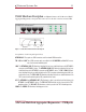
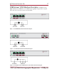
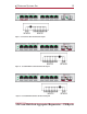
Step 3. Connect the other primary network cables to the primary SINGLEstream
™
S-100 RJ45 port
NETWORK B connector. The NETWORK-B LINK LED illuminates indicating link has been
established between the NETWORK B connector and primary NETWORK B device.
!!!:
The network is bidirectional Tx/Rx path sensitive and correct connection is indicated by
simultaneously illuminated
NETWORK-A
and
NETWORK-B
“
LINK
”
LEDs
.
W
hen con-
necting the second network device causes the first
LINK LED
to go out and both
LINK
LED
s are
NOT
illuminated, the network connection is backwards. Reverse NETWORK A
and NETWORK B connections and link will be established.
The NETWORK-A and NETWORK-B ACT LEDs illuminate as data is passed between the
primary NETWORK A and NETWORK B devices.
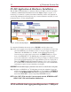
Step 4. Connect the redundant network cables to the redundant SS-100 RJ45 port NETWORK A
connector. The NETWORK-A LINK LED illuminates indicating link has been established
between the NETWORK A connector and redundant NETWORK A device.
NOTE: Let the “LINK” LED be your guide.
If you are properly connected,
NETWORK-A
and
NETWORK-B
“
LINK
”
LEDs
remain illuminated simultaneously.
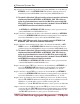
Step 5. Connect the other redundant network cables to the redundant SS-100 RJ45 port NET-
WORK B connector. The NETWORK-B LINK LED illuminates indicating link has been
established between the NETWORK B connector and redundant NETWORK B device.
!!!:
The network is bidirectional Tx/Rx path sensitive and correct connection is indicated by
simultaneously illuminated
NETWORK-A
and
NETWORK-B
“
LINK
”
LEDs
.
W
hen con-
necting the second network device causes the first
LINK LED
to go out and both
LINK
LED
s are
NOT
illuminated, the network connection is backwards. Reverse NETWORK A
and NETWORK B connections and link will be established.
The NETWORK-A and NETWORK-B ACT LEDs illuminate as data is passed between the
redundant NETWORK A and NETWORK B devices.
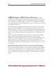
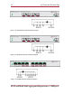
Step 6. Connect the primary TAP 1 port connector into the SS-200 RJ45 port NETWORK B con-
nector. The NETWORK-B LINK LED illuminates indicating link has been established
between the NETWORK B connector and the primary SINGLEstream
™
SS-100 .
Step 7. Connect the redundant TAP 1 port connector into the SS-200 RJ45 port NETWORK A
connector. The NETWORK-A LINK LED illuminates indicating link has been established
between the NETWORK A connector and the redundant SINGLEstream
™
SS-100 .
Step 8. Connect one SS-200 tap cable from the TAP 1 port connector into the IDS monitoring
NIC. The TAP 1 LINK LED illuminates indicating link has been established between the
SINGLEstream
™
SS-200 TAP 1 connector and IDS monitoring NIC. The
SINGLEstream
™
SS-200 TAP 1 ACT LED illuminates as data is passed to the TAP 1 IDS
.Step 9. Connect the other SS-200 tap cable from the TAP 2 port connector into the analyzer
monitoring NIC. The TAP 2 LINK LED illuminates indicating link has been established
between the TAP 2 connector and analyzer monitoring NIC. The SINGLEstream
™
SS-
200 TAP 2 ACT LED illuminates as data is passed to the TAP 2 analyzer.