
Owner manual

3/13/08 Rev. 1
Instruction / Installation Sheet
DataComm Electronics Phone/Video Module 70-0020
1x8 Coax 4x10 Phone Module
Step 1 Video
Attach a female F-connector onto the cable TV service or satellite service
incoming cable.
Screw the incoming cable with F-connector to the connector marked
“input”.
Using F-connectors, terminate all coaxial leads that have been pulled
through the top knockout to the video splitter.
Align the four mounting pins with holes in the back of the panel (upper
most position recommended) and snap into place.
Step 2 Telephone
Pull the telephone wires into the HCC panel from one of the side
knockouts.
Install the cable from the telephone company demarcation point to the
110 IDC marked from Telco.
Install the twisted pair cables from each location in the house to the
remaining 110 IDC connectors. Match the color-coding of the wires to the
colors on the 110 IDC connectors.
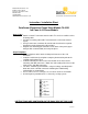
The wires should be punched down, using an industry standard punch-
down tool, to the 110 IDC connectors following the T568A wiring
configuration as shown below.
Line 1 is Blue, Line 2 is Orange, Line 3 is Green and Line 4 is Brown.
A RJ31X port is provided for line 1 seizure by security system.
Whi te / Bl ue
Blue
Whi te / Orange
Orange
White / Green
Green
Whi te / Brow n
Brown
INSTRUCTIONS ARE CONTINUED ON THE BACK SIDE OF THIS PAGE
DataComm Electronics, Inc.
6349 Peachtree Street
Norcross, GA 30071-1725
888.223.7977
770.662.8205
www.datacommelectronics.com